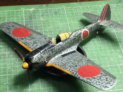
Nakajima ki43-II Hayabusa Hasegawa 1/72
|
|
|
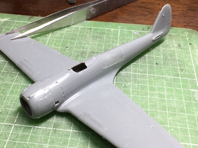
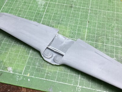
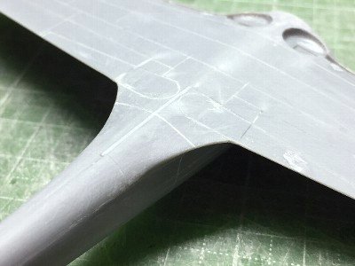
Since the vertical position of the wing was raised up, steps appeared between the fuselage and wing. Therefore, the lower part of the fuselage rearward of the wing was bent downward (green). Cut lines were applied in the front and rear portions of the lower wing part at the center line of the aircraft, and the front and rear portions were bent and opened downward (purple, blue). When they were bent, the cut lines opened, so shims were properly inserted. As the result, the wing was raised by 0.5 mm (.02"), and the fat belly was shaped up. |
 This photo shows kit original outline shape. |
 This photo shows kit original as well. The wing bulge is too thick. |
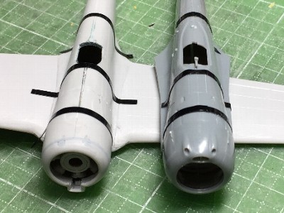 The original Hasegawa -II is compared with corrected Fujimi -I. Hasegawa firewall is a little wide and roundish. |
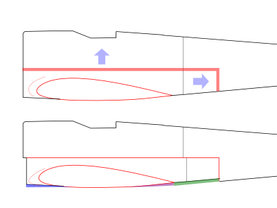 The upper figure : The red portion is cut and removed. The lower : the wing and fuselage parts was cut and bent (blue, purple and green). The upper front fuselage part protruding forward is cut off. |
|
|
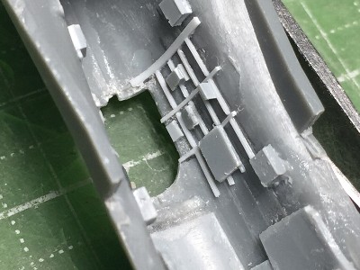
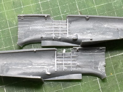 Frames and stringers were depicted with 0.3mm (.01") plastic sheet (white). Cut and bent lines can be seen. |
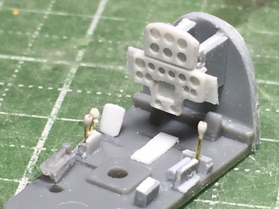 The instrument panels of -I and -II model were different. It was scrutchbuilt with plastic sheet. |
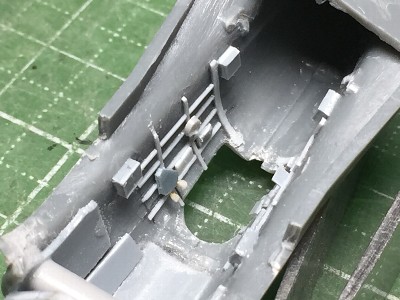 Details parts were added after left and right fuselage parts were glued. |
 |
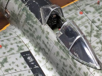
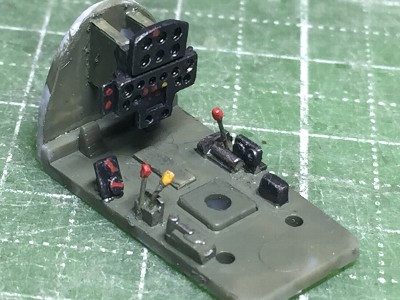 I think that the cockpit in this period was painted green gray. This Nakajima cockpit color is similar to FAA's Dark Slate Gray. |
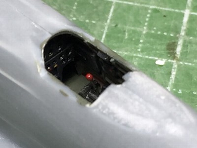 The instrument panel and floor was glued on the fuselage. Details are almost invisible. |
|
|
 The spar of plastic sheet was glued in order to hold the dihedral. |
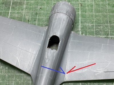
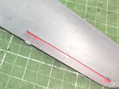
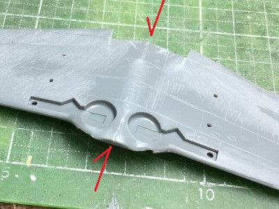 Cut lines were applied (red arrow). Then the forward and rearward portions were bent to open. |
 The wing was glued to the fuselage. |
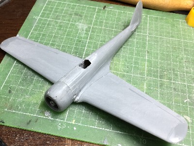
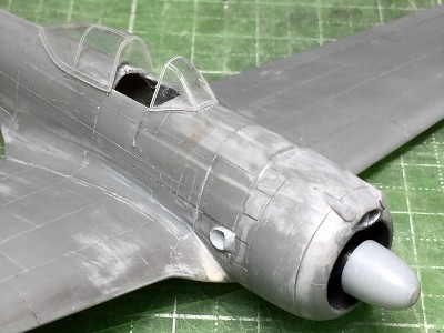
 The lower outline was confirmed in the side view. The connection between the cowl lower surface and the wing lower surface are important. |
|
|
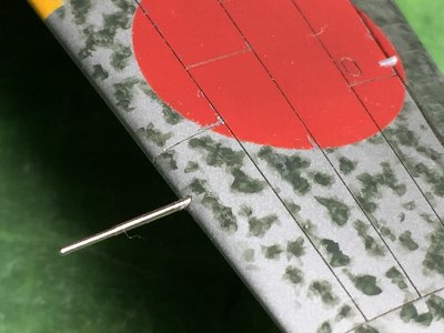
 I mainly used Creos's line chisel 0.1mm (.004") for panel line engraving. A needle was used for small access panel. |
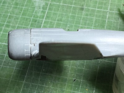
 The kit fillet was trimmed down in planar shape. The red shows the kit fillet. The new fillet outline is engraved at the blue line. |
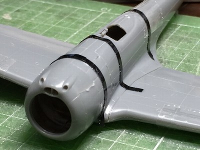
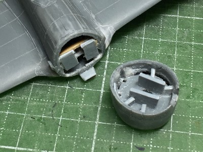
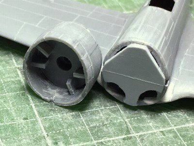 Guides were glued not to move the cowl. Note the cross section shape of the cowl end. |
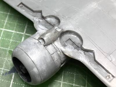
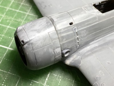
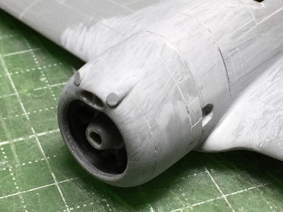 The wheel bulge was sanded to sharpen. CA glue and powder had been filled behind the bulge. After sanding, the kit portion was sanded off and CA glue appeared. The gun fairing was made of extended sprue. |
|
|
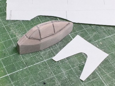 The wood mold was made of chemical wood. The print out of my drawings was cut and used for the gauge. |
 I adjusted the wood mold several times. 0.4mm (.016") clear styrene sheet was heat formed. |
 Frames were engraved with a handmade double needle. |
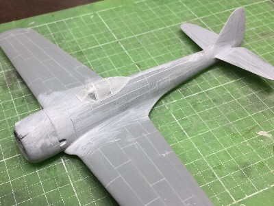 The horizontal fin was glued. |
|
The top and rear end of the vertical fin were cut off by 1mm (.04"). Then the hinge line was removed forward by 1mm (.04"). The height of the horizontal fin was lowered by 1mm (.04"). The gap at the fillet was filled with CA glue and powder. The planer shape of the elevator was corrected. |
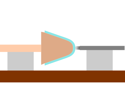 The top frame of the canopy was engraved as this figure. The canopy on the wood mold was fixed horizontal. Then the double needle was moved on the horizontal bench. |
|
|
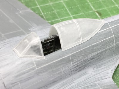
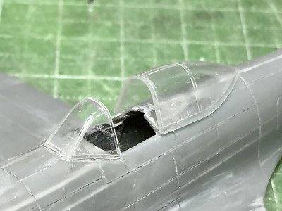
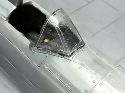
 This photo shows old canopy. From this angle, the defect was not recognized. |
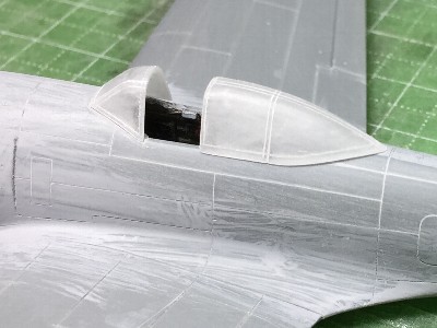
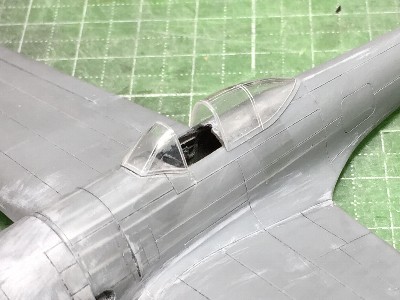
 This is the new canopy. Mmm, I can't recognize a differense. Well, modeling is a self-satisfying hobby.... |
 The oil cooler was basicaly kit part. The size and shape were corrected. |
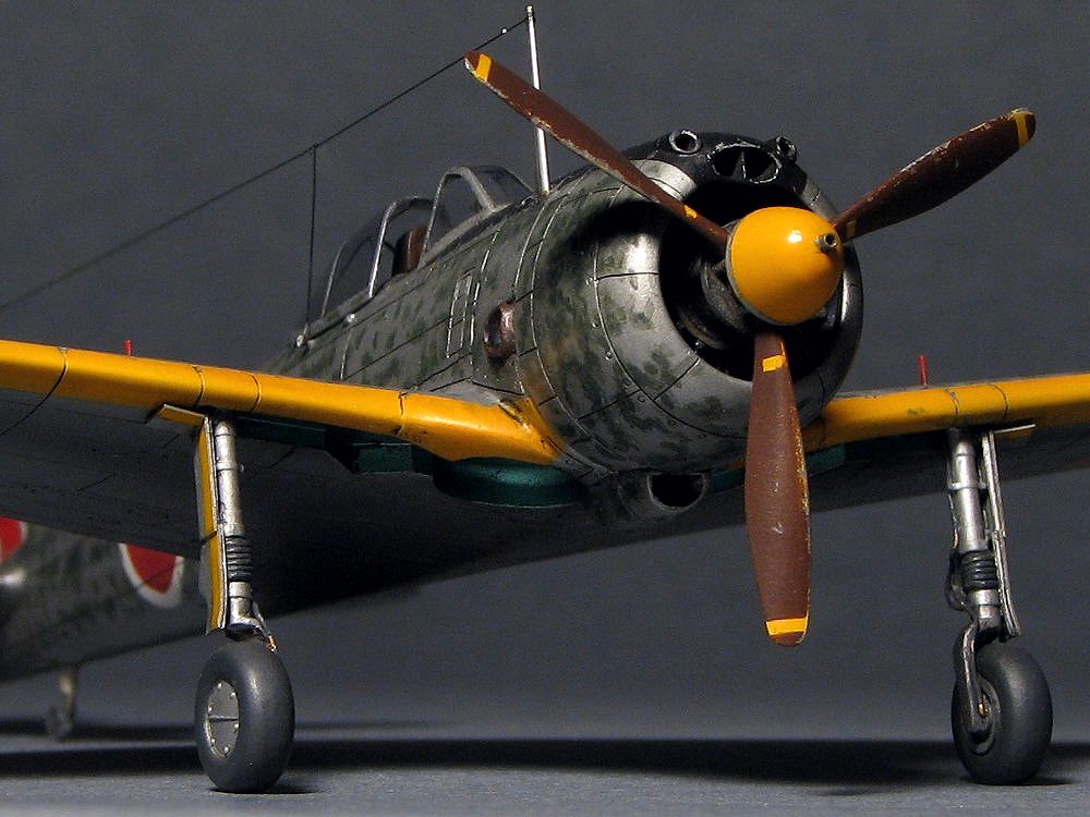
 The exhaust stack was glued. The spinner was made of plastic rod. The size was reduced after this photo. |
 The trailing edge of the cowl flap was sanded thinly. |
 The kit fuselage was shortened. So the position of the firewall was removed. |
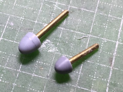 The 25th Sentai's Hayabusa didn't have the rear half of the spinner. |
 Rib tapes were depicted with dry decals. |
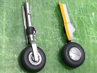
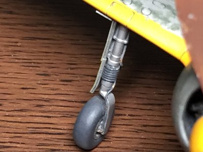
 The landing gear shaft was from the kit. But after this photo, the upper portion of the gear shaft was replaced with Tamiya Zero. |
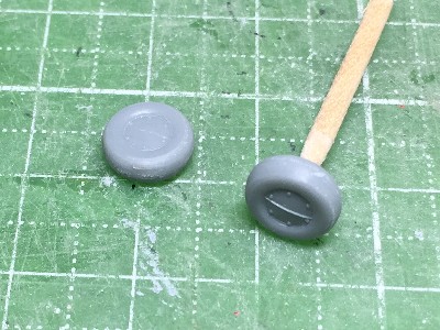 The wheel was from the kit as well. The diameter of the kit was a little small. CA glue was put on the tire tread. |
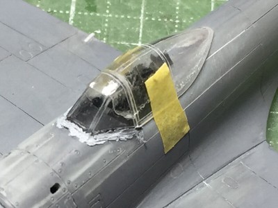 The wind screen was temporary fixed to the slide hood. Then the wind screen was glued on the fuselage. |
 Frames were engraved and the surface was polished. |
|
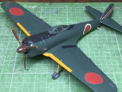
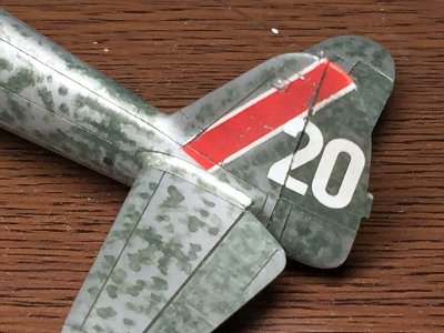
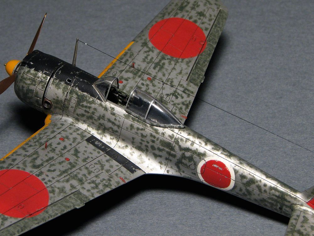
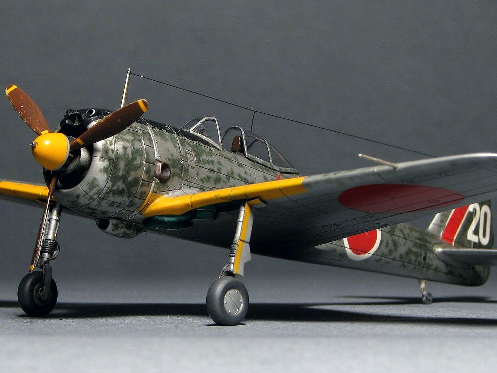
The size and position of the hinomaru (insignia) were different from -I model. The fuselage hinomaru is 70cm red and 85cm white in diameter. The wing hinomaru was uncertain. Judging from an analysis of photos, I assumed 140cm diameter and the distance from the wing tip was 140cm. IJA dark green and hinomaru red were the same as -I. Red brown of the propeller was 1:1 of #131 red brown and #335 medium sea gray. Orange yellow was Gaianotes's orange yellow with very small quantity of red. |
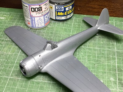 #8 silver and flat clear was sprayed. |
 Dark green was airbrushed on silver. BUT, the finish was completely different from the actual aircraft. |
 I tried to fix with retouching. BUT, it hardly improved. SO, this method was dismissed. |
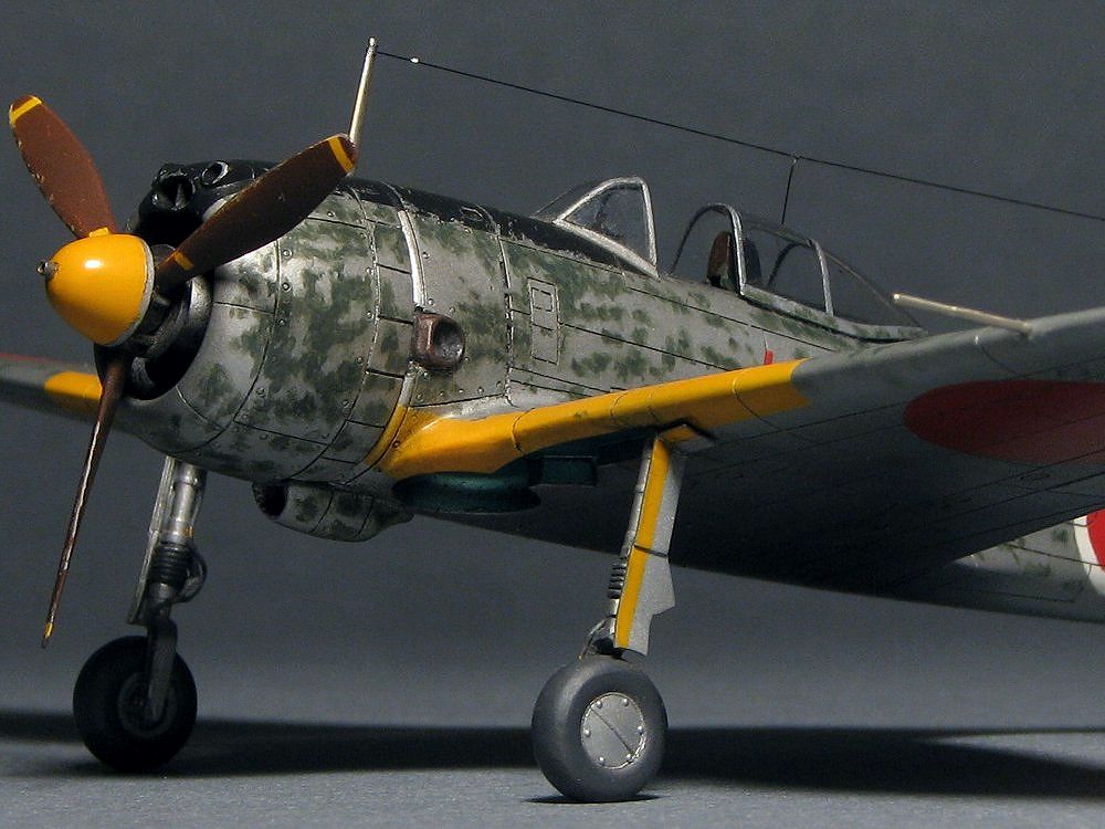
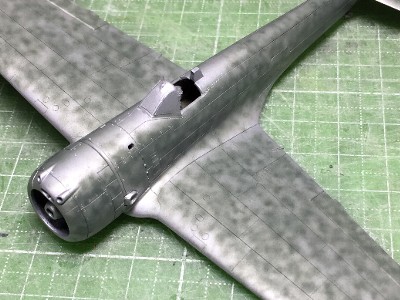
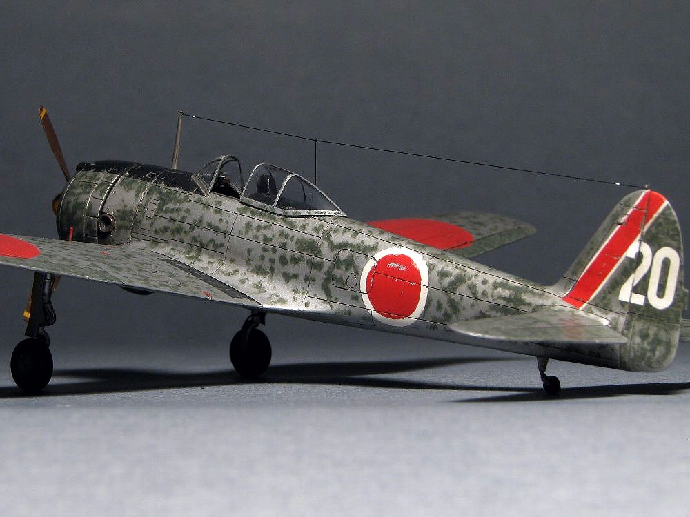
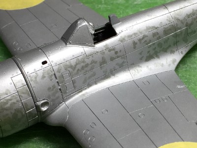 Silver with flat clear was airbrushed over again. Then mottle was painted with a fine brush. The first step was painted in a half and half of silver and dark green. |
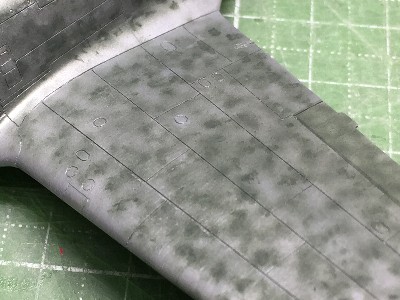
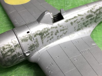 Next, thinly diluted dark green (without silver) was painted with a brush. Dark green was thinly paint over. After paint dried, next layer was painted again. As the result, the boundary of the dot became appropriately cloudy. |
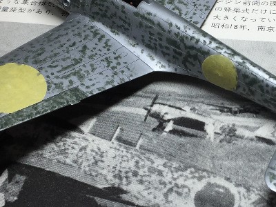 The photo under the model is #20 aircraft of the 25th sentai in FAOTW old edition. Fabric portions were darker than metal portion in this original photo. So I paint thickly on control surfaces. |
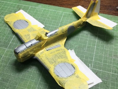 Markings were masked and airbrushed. |
 I painted in order of white, yellow-orange, red and black. Chipping was applied. Then flat clear was over sprayed. |
|
|
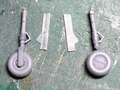 The upper portion of the gear shaft was replaced with Tamiya Zero. |
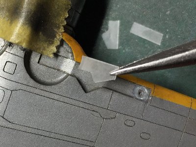 The gear cover was cut out as the same shape of my drawing. But, the kit gear well was different shape. Well, no one may notice this differense. |
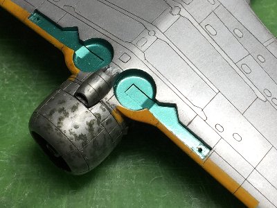 I think that the gear bay of the early to mid production of II model was Aotake, the inside of the cover was natural metal, and the cockpit was gray green. This coloring is the same as the early to mid Ki44 Shoki-II. |
 The gear cover of II model is different from I. The lower cover of I is bent at the center. The II's lower cover slides. |
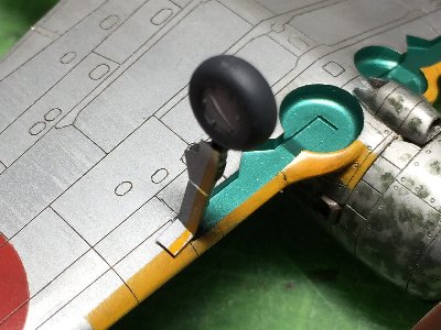 The gear and cover were glued on the wing. When the gear well was painted, the wing was masked with Scotch tape. It was cut with a knife after pasted. |
 The seat was scruchbuilt. The seat harness was Finemolds. |
 The seat was glued in the cockpit. I painted it in silver, but I don't know the color of the seat. |
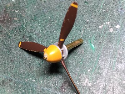 The details of the latter half of the spinner was unclear. It was somewhat a fiction. |
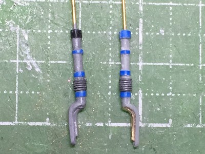
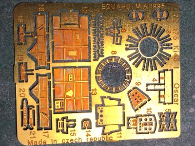 I just remembered I had bought a photo etching long ago. Only ignition cables was used. |
 The antenna mast was made of brass rod. |
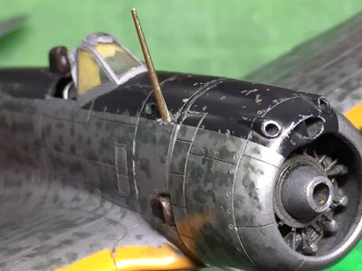 The antenna mast and ignition cable were glued. |
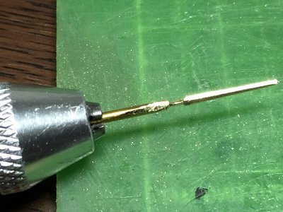
 The pitot tube was made of 0.6mm (.024") nickel silver rod. |
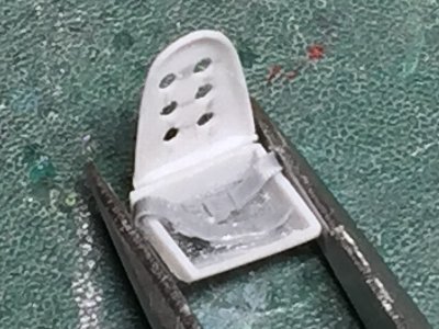
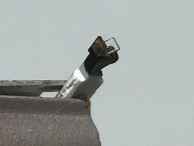 The main body of the gun sight was made of 1.0mm (.04") plastic sheet. The glass was 0.2mm (.008") clear plastic. |
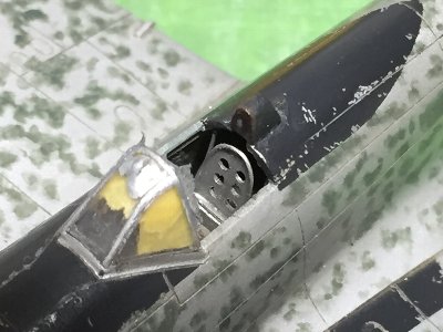
 The gun sight was glued on the cockpit. But unfortunately, it does not look well. |
 The brake line was 0.25mm (.01") lead wire. |
 The aircraft number "20" was custom made dry decals. Flat clear was sprayed on it. |
|
|
|
|
 |
 |
 |
 |
|
|