Nakajima Ki84 Army Type 4 Fighter Hayate Drawings


Go To 1/72 Hasegawa Modeling Note


Introduction

I had often had the feeling that existing drawings of Ki84 Hayate might not be accurate in the outline shape. Thus I decided to make drawings of myself. I only used original sources such as the copy of official manual and photos of actual aircraft.

These drawings are


Photographs

The most important source is a set of photos. Unfortunately, there was no good photo which satisfied three conditions of "long distance, right beside and clear". This might be one of reasons for inaccurate existing drawings. Anyway, photos were absolutely imperative. I'd show photos which I mainly used. The first one is the Otsu model of 104 Sentai with the camouflage scheme. The second is the late production Kou model captured by USAF. The third is the early production Kou model of 73 Sentai. The fourth is the mid production Kou model captured by USAF. The fifth is the Otsu model of 104 Sentai with NMF.


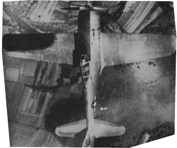
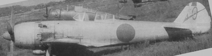
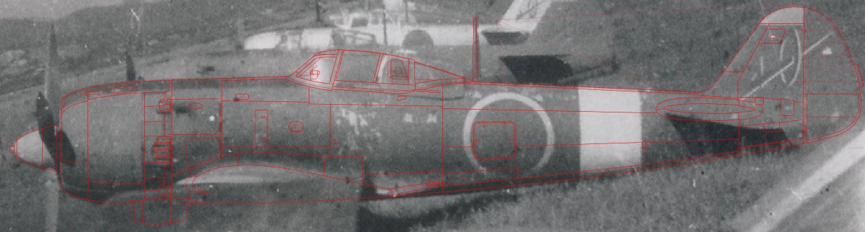
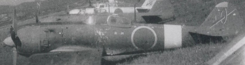
This photo was taken from a long distance enough and from right beside. So, this is the best photo for the outline shape. This picture is mirror-reversed image.


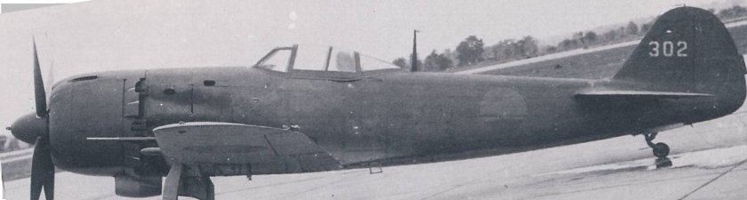
This photo was taken from right beside and clear. But it was taken from close range (approx 20 yd). I used this for details.


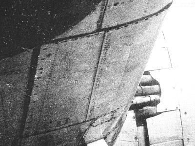
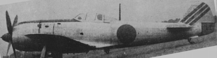
This photo was taken from right beside the tail fin. So this was helpful for the shape of the tail. Be aware that the rudder was not neutral. So the rudder chord looks like short.


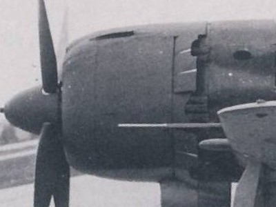
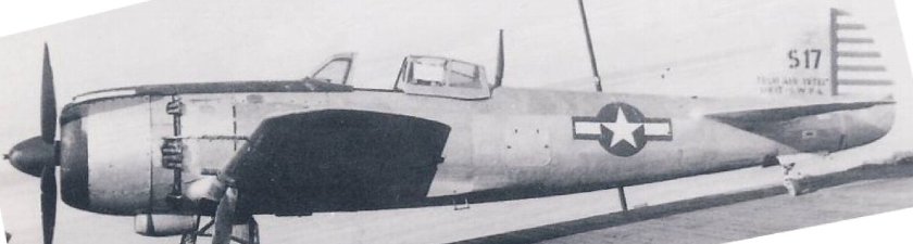
This photo was taken from right beside the nose. This aircraft became only existing aircraft.


This photo looks like a good shot for drawings at first view. But, it might be distorted by an unknown factor. The cowl is too long and the spinner is short. The rear fuselage is short but the fin is wide.


If you feel a sense of discomfort when you look at above photos, you have great eyes. As a matter of fact, these four photos with the exception of the first photo were removed perspective distortion using image modification software ( free software GIMP2 ).


The total length of Hayate

The value of total length is absolutely necessary for making drawings. However, the total length of Hayate is mysterious. Most of references describe 9,740mm which is written in the official manual of IJA. But most of existing drawings are drawn as 9,920mm.

In such a case, I usually use station diagrams of the fuselage. Hayate's station is described in ref.-4 "Aero Details 24" of Dainippon-Kaiga. But, they were not match to photos of actual aircraft when they were superimposed. On the other hand, USAF measured the captured Hayate as 32.3 ft (=9,850mm) (ref.-5). In addition, another reference describes that the length from the wing leading edge to rudder hinge is 9,070mm and this value was written in the official manual. This value is not match to station diagrams.

Mmm.. What should I do?


The result

I tried to make drawings satisfying above data as much as possible. The result is the following figure. The total length is 9,860mm including the rudder tab. And it is 9,860mm without tab. The station diagrams are mostly correct excluding rib #8 to #9 and #17 to #20. Details were traced from the second photo. The max heights of the fuselage match 1,450mm and 1,740mm (with wind screen) which were written in ref.-5.


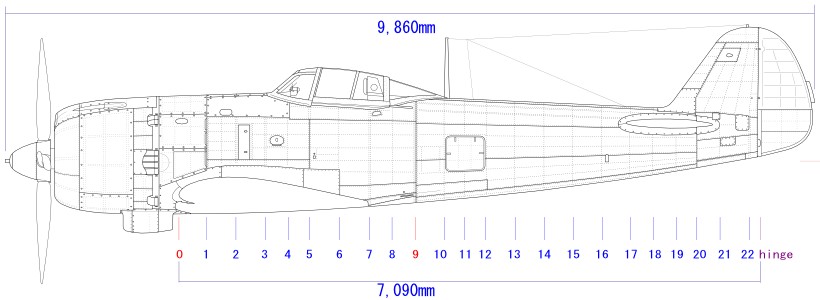
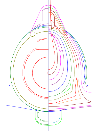
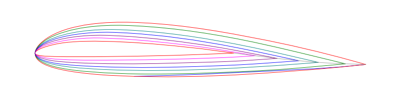
Purple lines of the lower figure are one of existing drawing. Pale blue is my drawing.


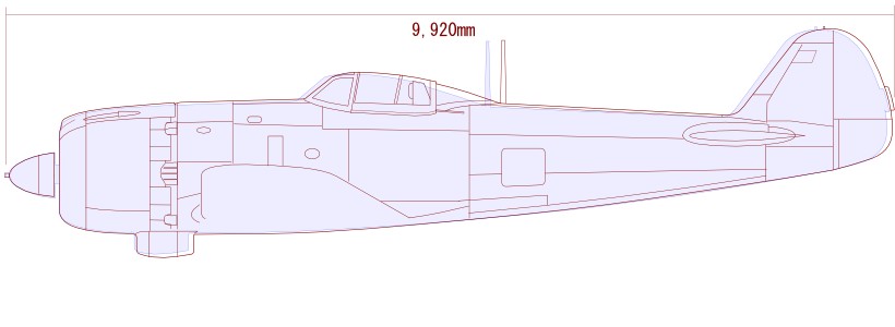
I considered about 9,740mm and 9,920mm.


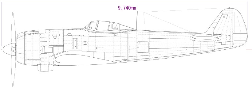
The rudder is replaced with the rudder frame drawing in ref.-4. The total length became 9,740mm. I guess that this style might be the trial production.


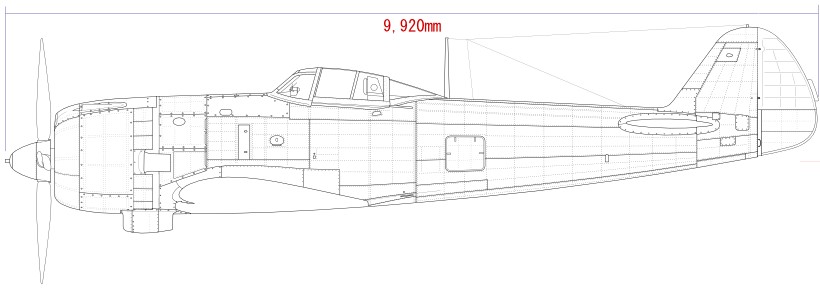
The rudder is extended to become 9,920mm total length. This figure looks like increasing trial production.


Finally, my drawings is superimposed on the first photo.


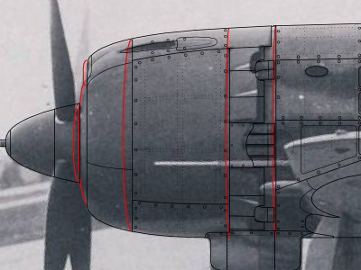
Original photos should be removed perspective distortion when they are used in drawing works. For example, as for the following picture, the cowl was seen from rearward, so vertical panel lines and the leading edge of cowl move away.


Side view drawings

  • Anyone can use my drawings without permission for any purpose including commercial use.

  • Fuselage station diagrams were verified with walk around photos. The length between #8 to 9 is assumed 290‡o, #17 to 18 is assumed 285mm, #18 to 19 is assumed 280mm. Other lengths are the same as ref.-4. The lengths of cowl are rounded off by 5mm pitch.

  • The large size oil cooler was introduced on the late production of Kou model and it continued to Otsu model. The second photo aircraft is this type.

  • The incidence and height of the horizontal stab were unknown. They were presumed.

  • The stab was inserted in the fuselage slot from rearward and then the tail unit including the vertical fin was assembled. Thus the front spar of the stab was connected to the fuselage #18 frame and the rear spar was connected to #20 frame.

  • The airfoil was Nakajima NN-2 (ref.-5). I carefully assumed its shape from ordinates table in ref.-5 and actual aircraft photos. The wing chord was 2,430mm. The wing thick ratio was 16.5% (root) and 8% (tip). The incidence is 2 deg. (root) and 0 deg. (tip). The dihedral is 6 deg. These data were described in ref.-5.


The cross section drawings

  • The nose gun was set 530mm to the center line. The fire line was on the circler arc of 1408mm diameter.

  • The size of cowl opening was assumed from the actual photo in ref.-1 p.34.

  • The lower half of the cowl is true circle (section A to C).

  • The maximum width of the cowl was 1,260mm (ref.-5). The Ha45 engine was 1,180mm diameter. So the gap was 40mm. The maximum width of the fuselage was described as 1,220mm (ref.-4). It was assumed that the width of the fire wall.

  • The width of the canopy was calculated from photos taken from rearward. Hasegawa 1/48 and 1/32 kit canopy is a little wider.

  • Cross sectional shape of #13 to 17 were traced from the photo of the fuselage inside.


Top view drawings

  • The wing chord was described as 2,430mm (root) and 1,460mm (tip of 5,030mm from CL) in ref.-5. But it was too tapered compared with the photo. I assumed the tip was not 5,030mm but 5,300mm.

  • The side line of the cowl was the same as the lower line in the side view. Because the lower half of the cowl cross section shape was true circle.

  • The side window of the slide hood was bent at the line which located 20cm forward from the hood rear end.

  • The wing span was 11,238mm on the horizontal plane and 11,300mm on the wing ref. line. The wing gun station was 2,000.

  • The panel lines were referred to existing aircraft. The port and starboard lines were different. They were shown in blue lines. The differences were thought that port lines were added at restoration works.

  • Rivet lines on the wing leading edge fuel tank are different from existing drawings and frame drawings of official manual. But my drawing was based on walkaround photo. I guess that the manual described the experimental production.

  • There were variations in fasteners of the wing gun panel.

  • The position of the elevator hinge line was assumed from the photos and side view drawings. Stab and elev chord were assumed as well.


This picture is a corrected top view air to air photo. It is corrected to equalize left and right wing tip chords.


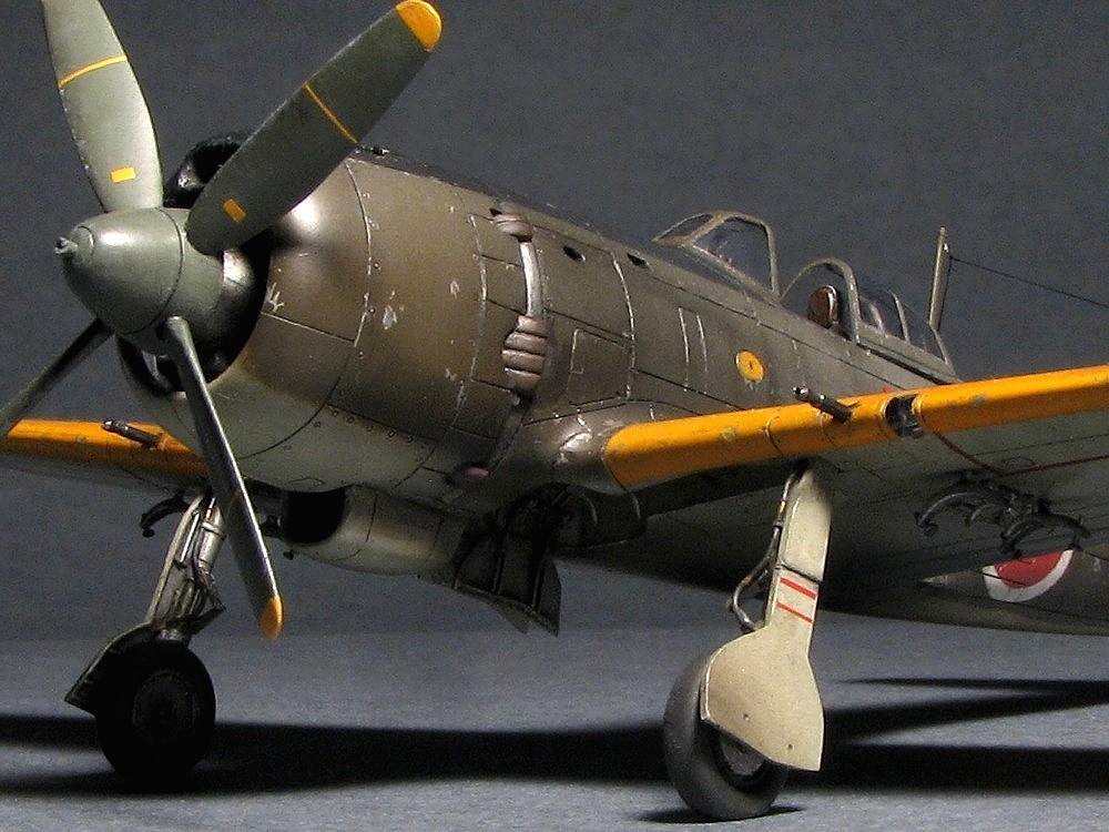
Following color photos are restored aircraft of Chiran Museum. The monotone photo is WW2 original.


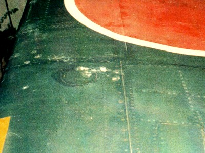
The wing fuel tank cap is circle shape. Double rivet lines can be seen on the tank.

There are two set of these double rivet lines on the tank. The panel line parallel to the leading edge is only lower side.

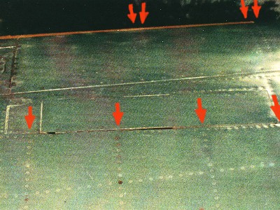
Numbers and positions of tank and wing ribs are different.

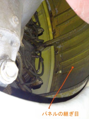
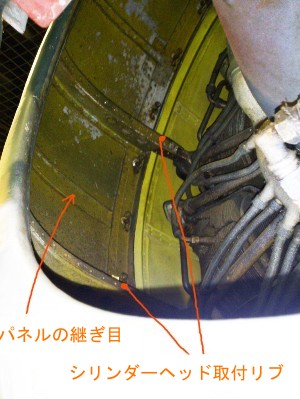
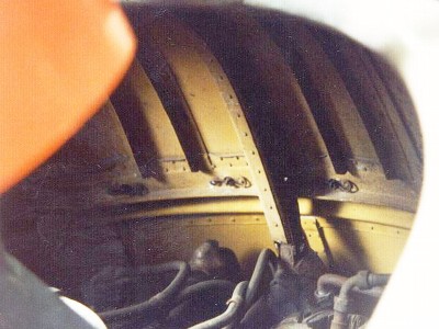
This photo shows the port inside of front cowl. The left is upside, the right is downside.


Bottom view drawings

  • The airfoil of Ki-84 is Nakajima NN-2. The vertual airfoil at sta.0 (CL) was not match to the side view silhouette. I assumed the airfoil of this portion was partially modified.

  • The thickness ratio is 16.5% (root) and 8% (tip). The dihedral is 6 deg. The incidence is 2 deg. (root) and 0 deg (tip).

  • Positions of the main and rear spars were located at fuselage #2 and #5 frame. The rear edge of the flap was located at #7 frame.

  • Each wing rib was perpendicular to the wing ref plane. ribs were drawn as projection to the wing ref plane in my drawings.

  • Upper and lower panel lines at the wing tip were differ from one another.

  • There was not a blister for the gear actuation link but the small door at early production model. Details of this door were unknown. My drawings only show the blister.


Front and rear view drawing

  • The front and rear shapes of the canopy were carefully determined.

  • Panel lines on the spinning (front part of the cowl) were not symmetrical.

  • The maximum chord of the propeller blade was 270mm. There were three values as for the diameter in some references. That is 3m, 3.05m and 3.1m. I don't know the correct answer.

  • The leading edge of the flap was straight line. On the other hand, the trailing edge was curved.


Airfoil

The ordinate table of Ki-27's Nakajima NN airfoil is in ref.-5. But I consider that airfoil of Ki-84's NN wing and Ki-27's NN wing are slightly different. Because Ki-27 airfoil didn't match to Ki-84 side view photos especially in the latter half. I assumed Ki-84's airfoil that the front half was like Ki-27 and rear half was like NACA2200. As the result, the airfoil became nearly NACA2300. Following figures are these assumed airfoil for Ki-84.


The root virtual airfoil was shown in red line. The blue line shows the actual airfoil at the root. This is the same as the side view silhouette.


References

In addition to the following list, actual measurement values of restored aircraft by Ichiro Hasegawa and Rikyu Watanabe were referred. Phots of the restored aircraft of this site were referred as well.

http://geta-o.jp/WB/P&F/HAYATE/WB-HAYATE.html
1 Famous Airplanes Of The World No.19 Army Type 4 Fighter Hayate- Bunrin-do
2 Famous Airplanes Of The World (old edition) No.20 Type 4 Fighter Hayate Oct. 1971- Bunrin-do
3 History of Pacific Warfare Series 46 Type 4 Fighter Hayate4-05-603574-1 Gakken
4 Aero Detail No.24 Nakajima Type 4 Fighter Hayate4-499-22684-8 Dainippon-kaiga
5 Military Aircraft Mechanical Series No.7 Hayate / Type 97 Heavy Bomber / Type 2 Flying Boat4-7698-0637-X Kojin-sha
6 Model Art Extra Edition No.283 IJA Type 4 Fighter Hayate- Model Art
7 Model Art Extra Edition No.493 Nakajima Type 4 Fighter Hayate- Model Art
8 T-2 Report on Frank-1(Ki-84),T-2 Serial No.302 Interim Report No.3- Headquarters Air Materiel Command


Go To 1/72 Hasegawa Modeling Note


HOME