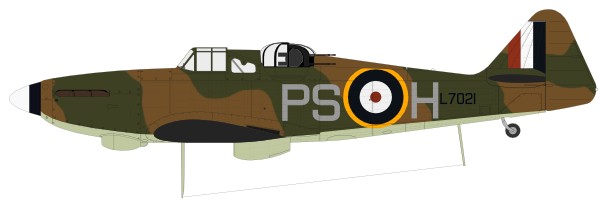
Boulton Paul Defiant Mk.I Airfix 1/72
|
|
|
|
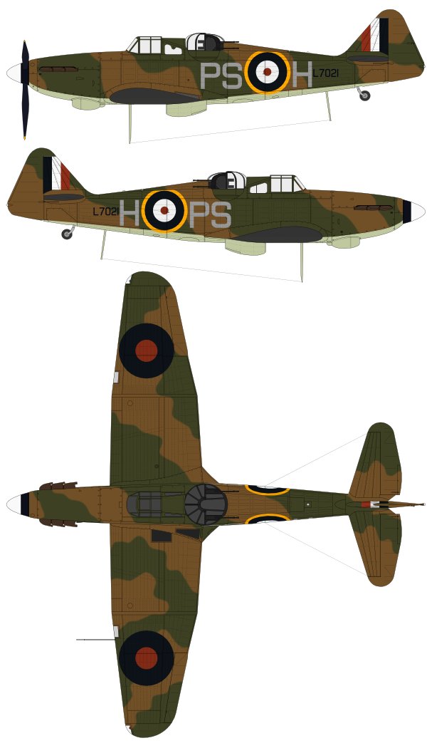
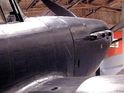 Note the distance of the rear exhaust and cowl. |
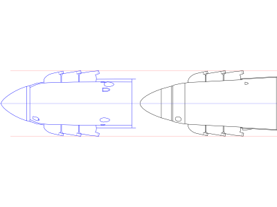 The left is Spitfire Mk.I. The right is Defiant. They are the same scales. |
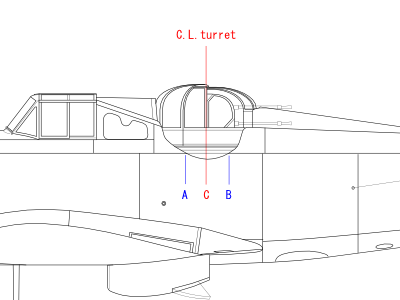 C is the axis of the turret. BC is larger than AC, so the width A is wider than B. |
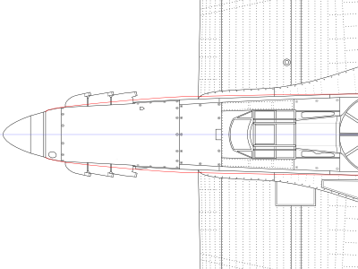 The black line is a actual aircraft. The red line is Airfix kit. |
|
|
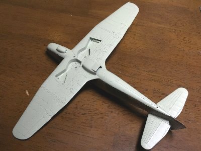
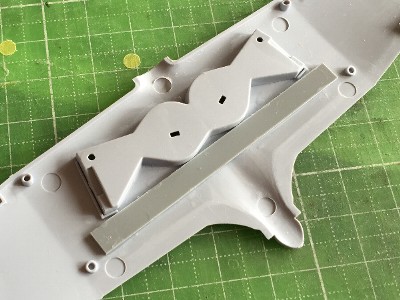 The kit lower wing which I bought was distorted. I bent it with my hands and plastic sheet was glued for reinforcement. |
 The cockpit was straight from the box. The surface was peeled off with sandpaper to sharpen kit panel lines. |
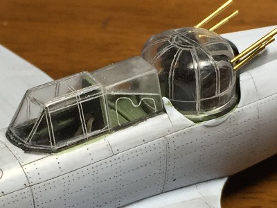
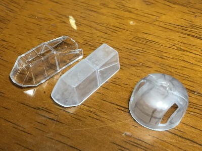 Canopy frames of the kit clear parts were sanded off. |
 Canopy frames were engraved with handmade double needles (0.3mm (.01") wide). |
|
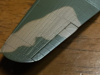
Because of sanded frames, the canopy height became a little low. 0.4mm (.015") clear plastic sheet was glued on the lower edge. The rear retractable canopy was cut off with etching saw. It wasn't adjusted the height. As the result of that, the gap between the slide hood and retractable canopy was depicted.
|
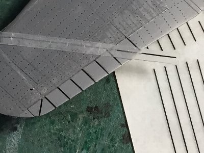
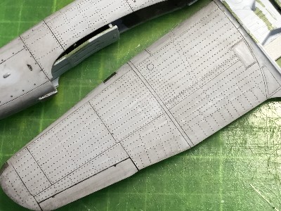 There are nine stringers between the front and rear spar of the main wing. But they are too many for the 1/72 model. I reduced them to seven. Well, I was a convinced criminal. |
 These templates were cut by home use cutting machine. |
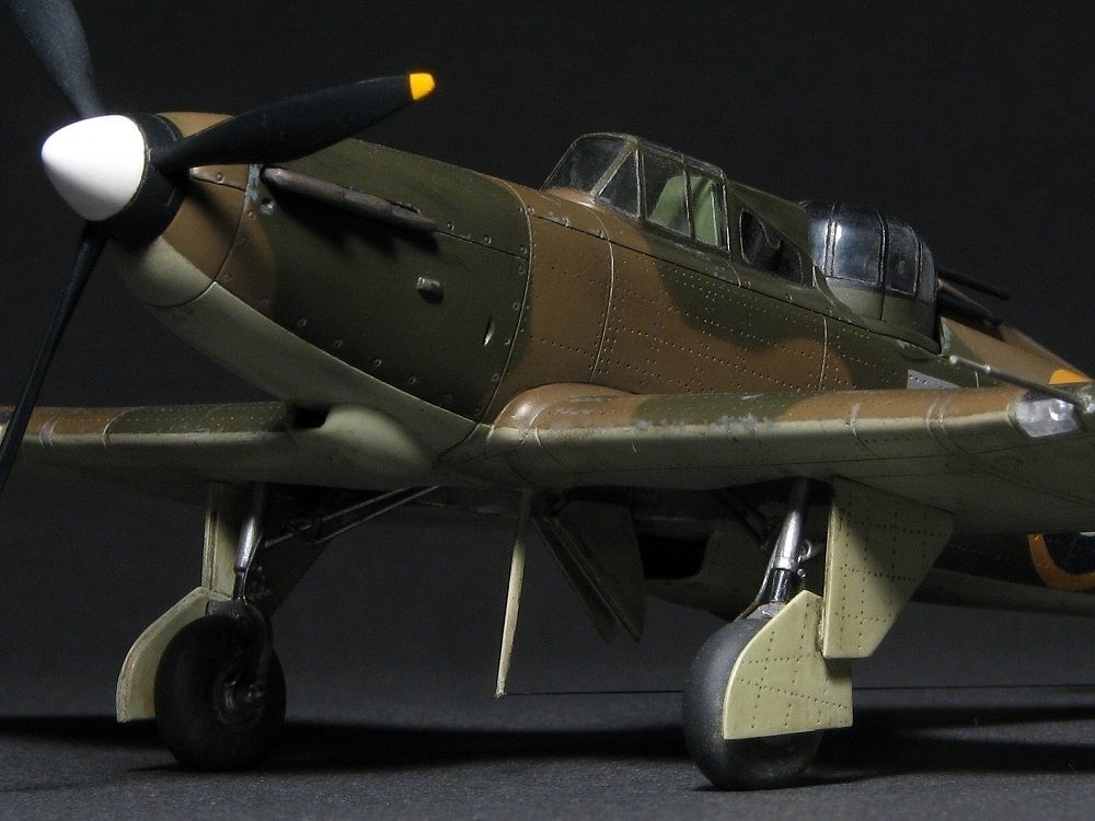
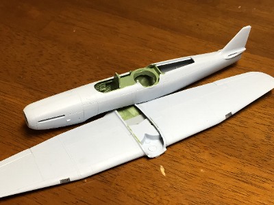
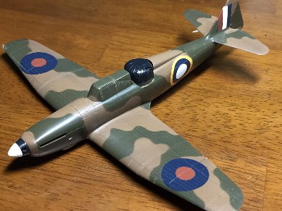
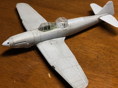 In this photo angle, Defiant looks unexpectedly beautiful and grace. The reason may be her long rear fuselage. |
|
|
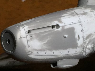
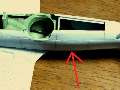 The kit max width was rearward the turret (red arrow). |
 The fuselage side rearward the turret was sanded. |
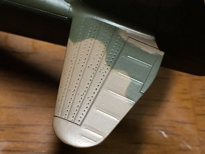
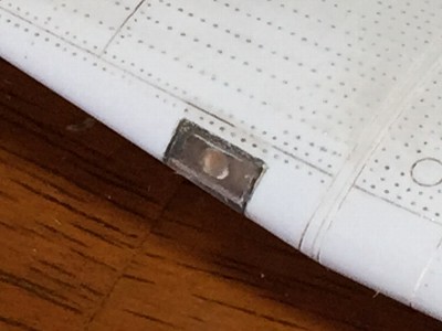 The landing light was replaced with heat formed clear plastic sheet and punched out aluminum sheet. |
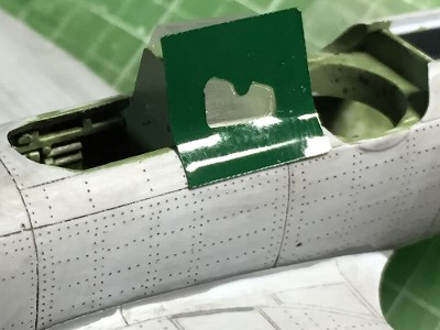
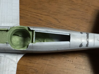
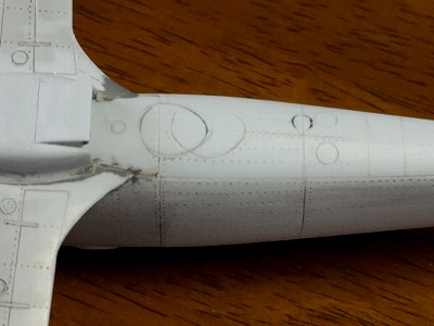 The escape hatch was removed rearward. The dark line is kit original. |
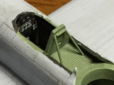 The instrument panel was kit decals. Rods of extended sprue were added on. |
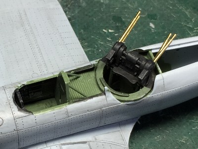 Gun barrels were router lathed brass rods. |
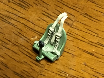 The pilot seat was from kit. The harness was Fine Molds' Nano Aviation Series. |
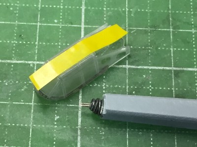
 The canopy and turret were almost finished. Clear parts were polished with rubbing compound. |
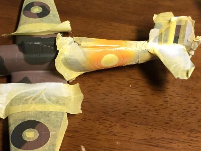
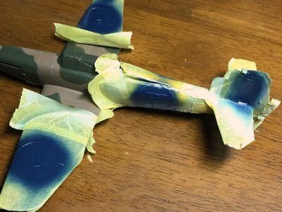
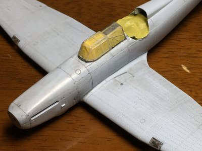 Canopy windows were masked with scotch tape. Yellow masking tape was a masking for inside. Canopy parts were temporally fixed with wood glue. |
 Mr. Surfacer was thinly sprayed to find blemishes. Fasteners of the cowl were engraved with beading tool. |
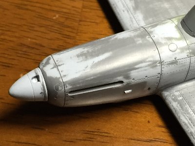 The spinner was enlarged with 0.3mm (.01") plastic sheet. |
 Rib tapes of aileron and elevator were depicted with dry decals. |
|
Recent research revealed there were many variations of Sky shade in this period. No 264 Sqn Defiants might had been painted Black and White undersurface and repainted with "Sky". So there is a possibility that the shade of this paint was not proper Sky. But I didn't know the correct fact. Of course, I painted in Sky. |
 |
|
|
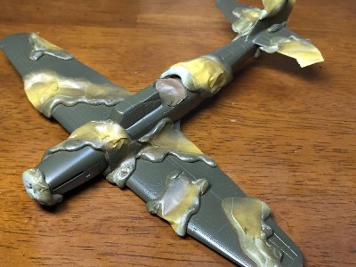 First, Dark Earth was sprayed. Then it was masked with Bru Tack. |
 Dark Earth was Mr. Color #22 and 30% of Yellow. |
 The thickness of dry decals matches delicate depiction. |
 |
|
|
|
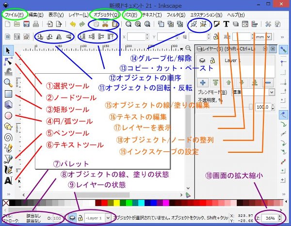
Basic window There are commonly used tools. Sorry, this is Japanese. So translations might not match to original. Anyway, icons may be the same.
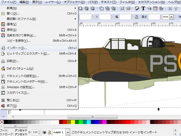
Page set up, Import of a pic The first step is Page set up. I always make drawings in 1/48 scales. It is set up in A4 size using "File" => "Set Up Document".Next step is Import. In this tutorial, I import my illustration as a picture and trace it. Well, this is an odd setting. Click "File" => "Import" => pick up a picture. The picture is put on the "Layer 1". If you click "Eye icon", this layer is hided (non-display).
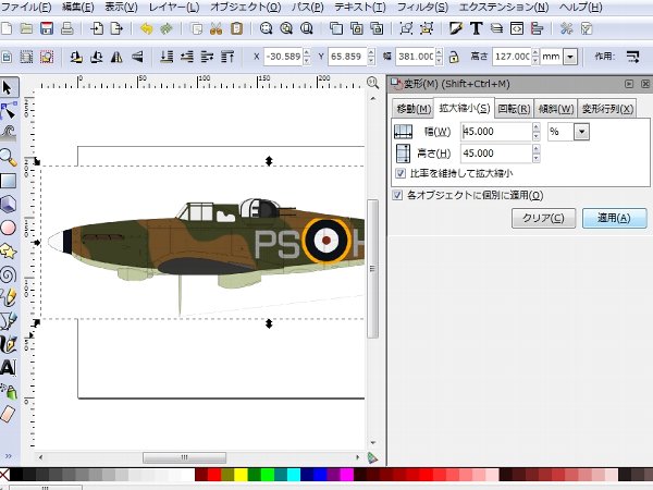
Zoom in/out of the picture The imported picture is larget than proper 1/48 size. So the picture has to be zoomed out. Click "(1) Pointing tool" and click the picture, "Object" => "Mutation" => "Zoom in/out".
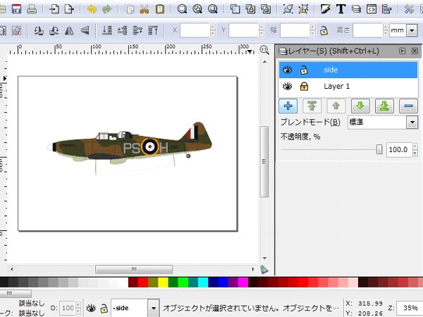
Set up drawing layer Click "(17) Layer" icon , then the layer window opens. Click "+" icon and set up a new "side" layer for drawings.
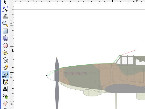
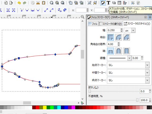
Input an outline Click "(5) Pen tool" icon. Click a starting point (L.E. of the spinner) of the outline, then click next point and so on. If you finally click starting point (small box), the outline become a polygon object. Note that in this tutorial, the picture layer is 50% opacity.
|
|
|
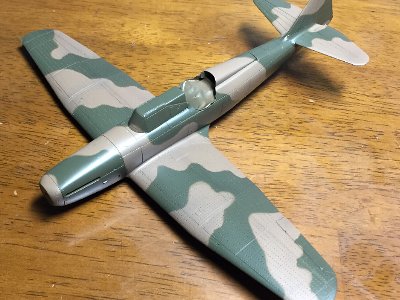
 The under surface was Sky. Then Flat Clear was oversprayed. |
 First step was masking for White portions including basecoats. |
 White was sprayed on the fuselage roundel and fin flash. Then Yellow was sprayed. |
 Yellow and White were masked and Blue was sprayed. |
 Dull Red was painted on the wing roundel and fin flash. The fuselage roundel would be decals. |
 The code letter was masked with machine cut sheet. This is positioning. |
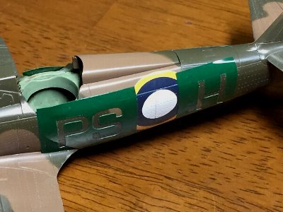 Then cutting sheet was pasted. |
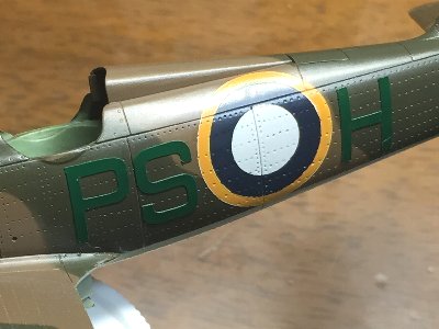
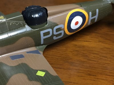 Code letter and decal were finished. |
|
|
|
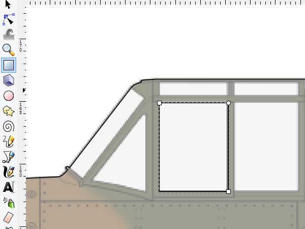
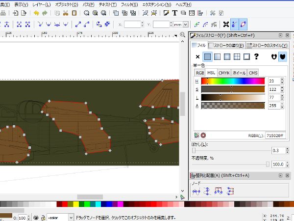
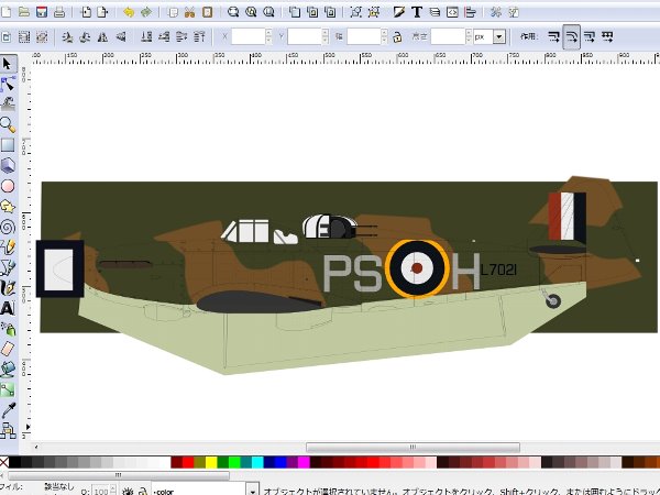
Camouflage paint Set up a new layer of painting. Draw objects and paint them. Airbrushing effect is set in "(15) Fill/Stroke Edit window". Color tone is also edited in this window.
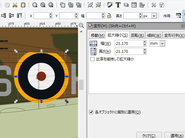
Markings The roundel is drawn with "(4) Circular Arc tool". Adjust its size with "Object" => "Mutation".
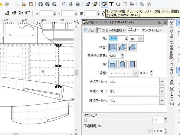
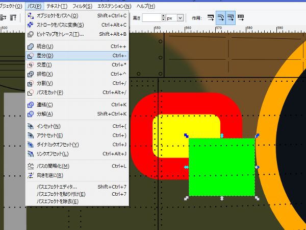
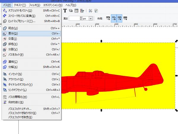
Masking The camouflage paint objects run off the edge of fuselage drawings. So the Masking layer is newly set up and hides them. Cut off Red object from the Yellow rectangle with "Path" => "Difference". Then repaint the new object in White. This Masking layer put on the Paint and Marking layer and under the drawings, rivets and fasteners layers.
|
Next tutorial is 3D Gradation.
|