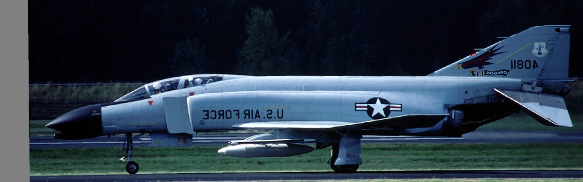
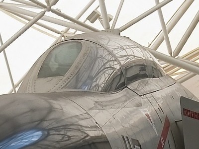
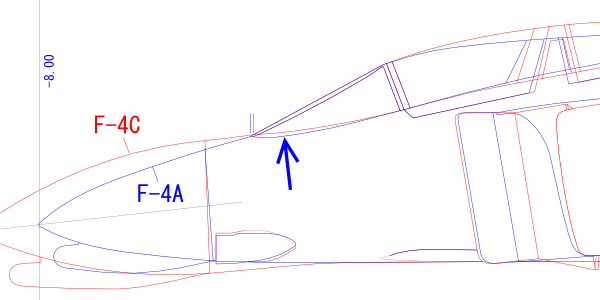
This is F-4C from Airliner's Net. When calculated from the view of the tail and wheels, the distance is 150m (160yd) or more, just beside the cockpit, and the error of perspective is small.
McDonnell Douglas F-4 Phantom II Drawings part 1
|
|
|
This is F-4C from Airliner's Net. When calculated from the view of the tail and wheels, the distance is 150m (160yd) or more, just beside the cockpit, and the error of perspective is small. |
|
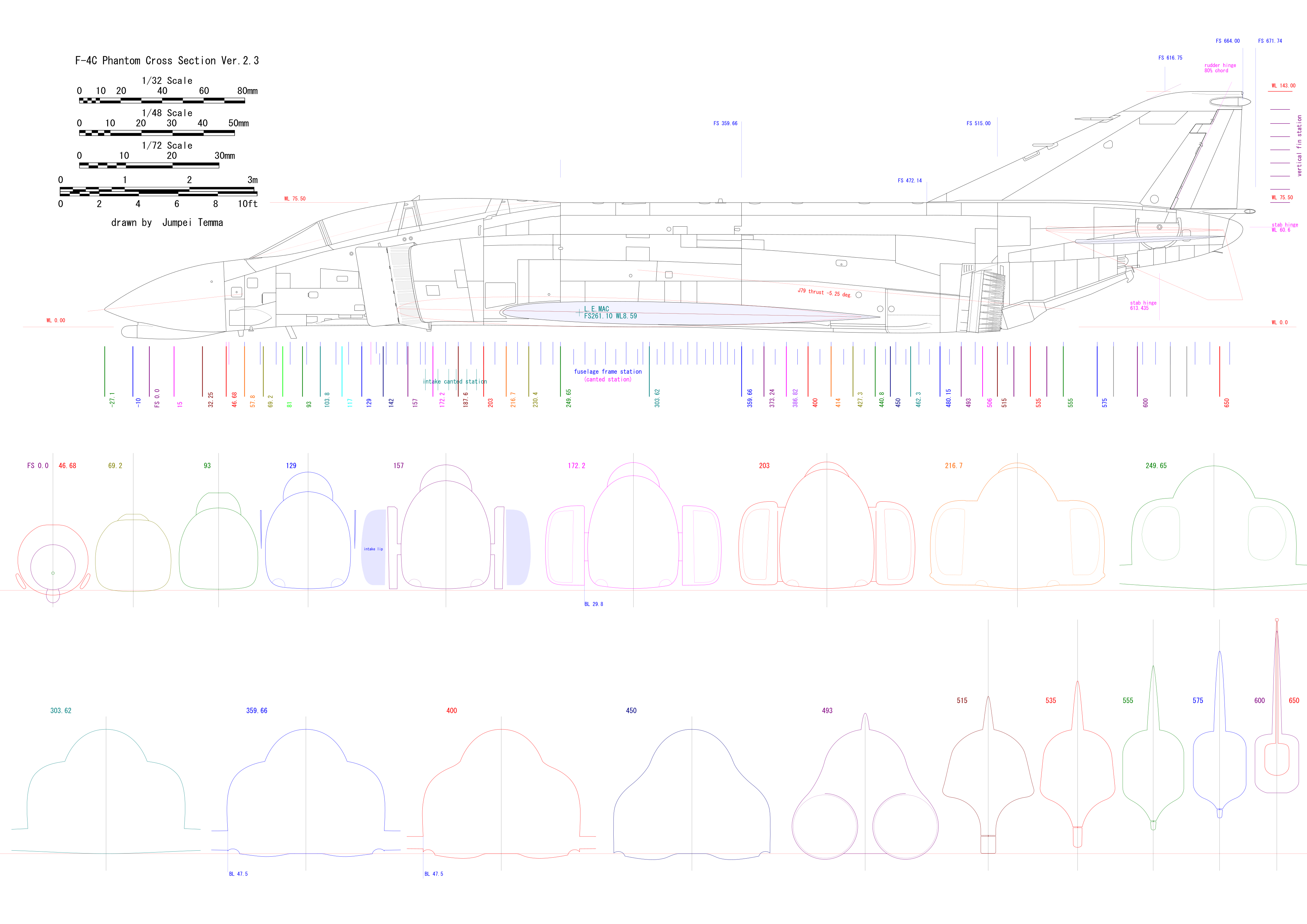
The fuselage height can be read as WL75.5 from the A model general arrangement. As for the height of the wing position, the height of LEMAC is WL8.59 in the general arrangement. The inner wing dihedral is 0üŗ, so LEMAC should be on the wing ref. line, but it does not match the wing position of the fuselage side view factory drawing. Also the fuselage cross-section outlines are slightly different from each other in each drawing. What do I do?
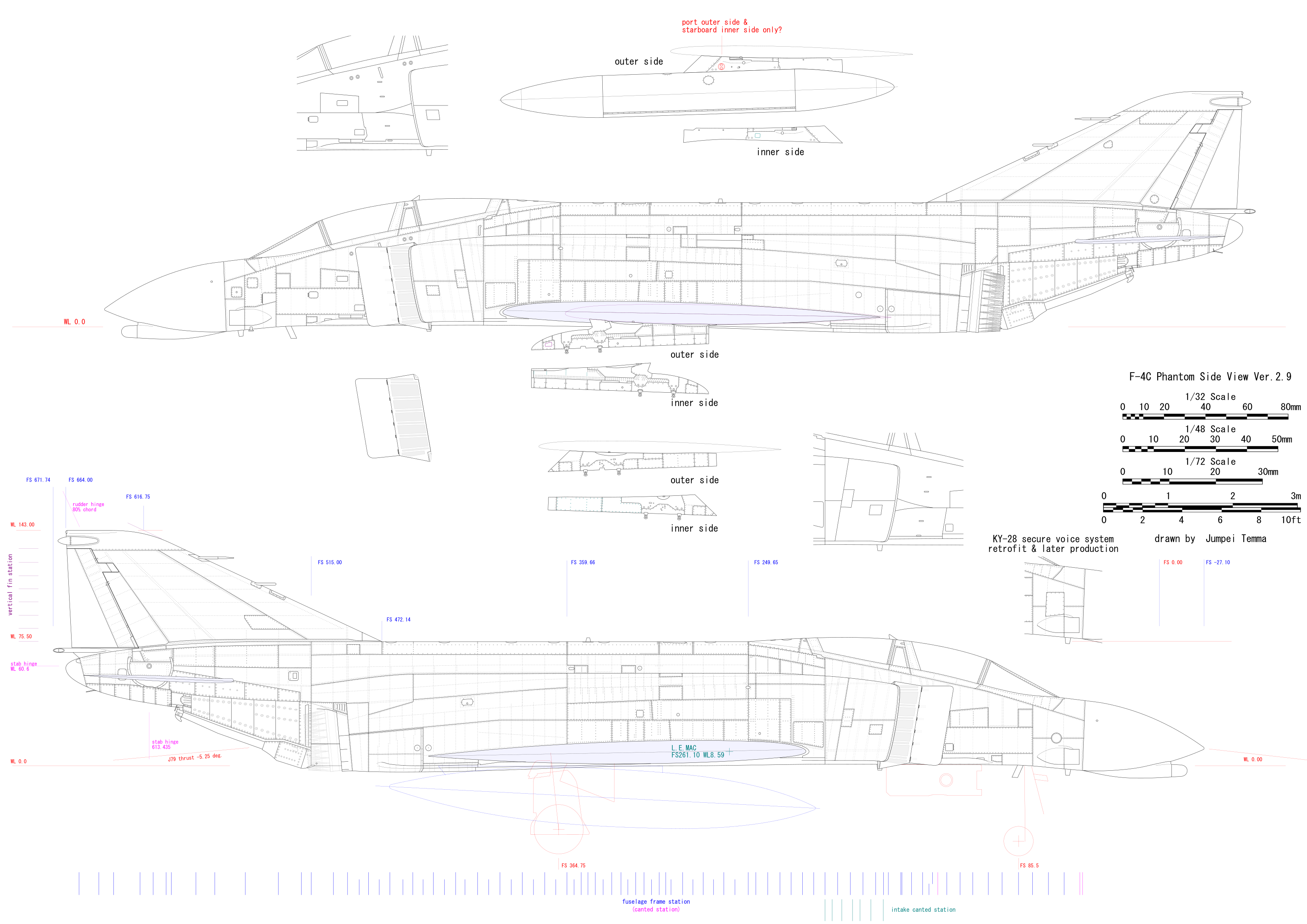
In my drawing, it is important how to superimpose the photo and factory drawings. That is the picture below. |
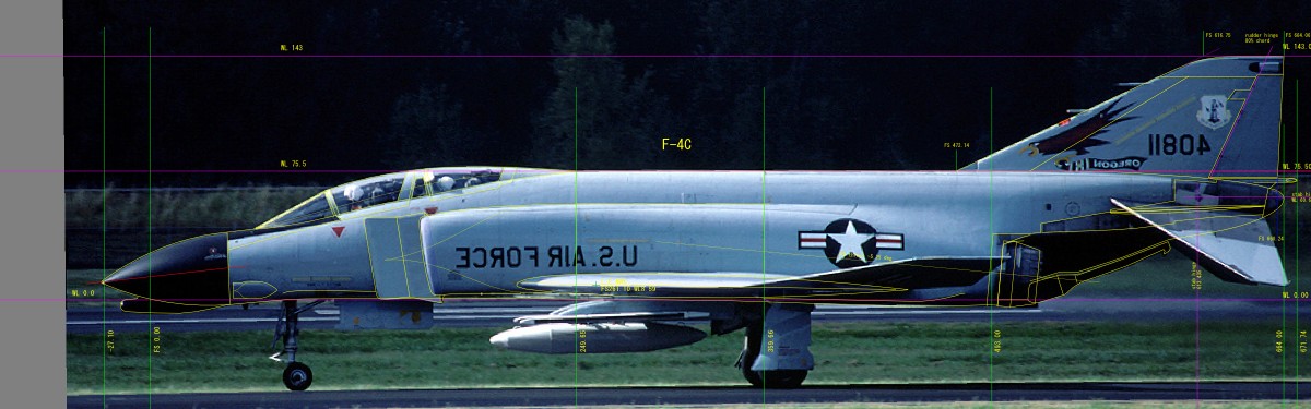 The gap between my drawing and photo near the jet nozzle is the result of removing the perspective error. The deviation width can be estimated from the appearance of the left and right stabilators. |
|
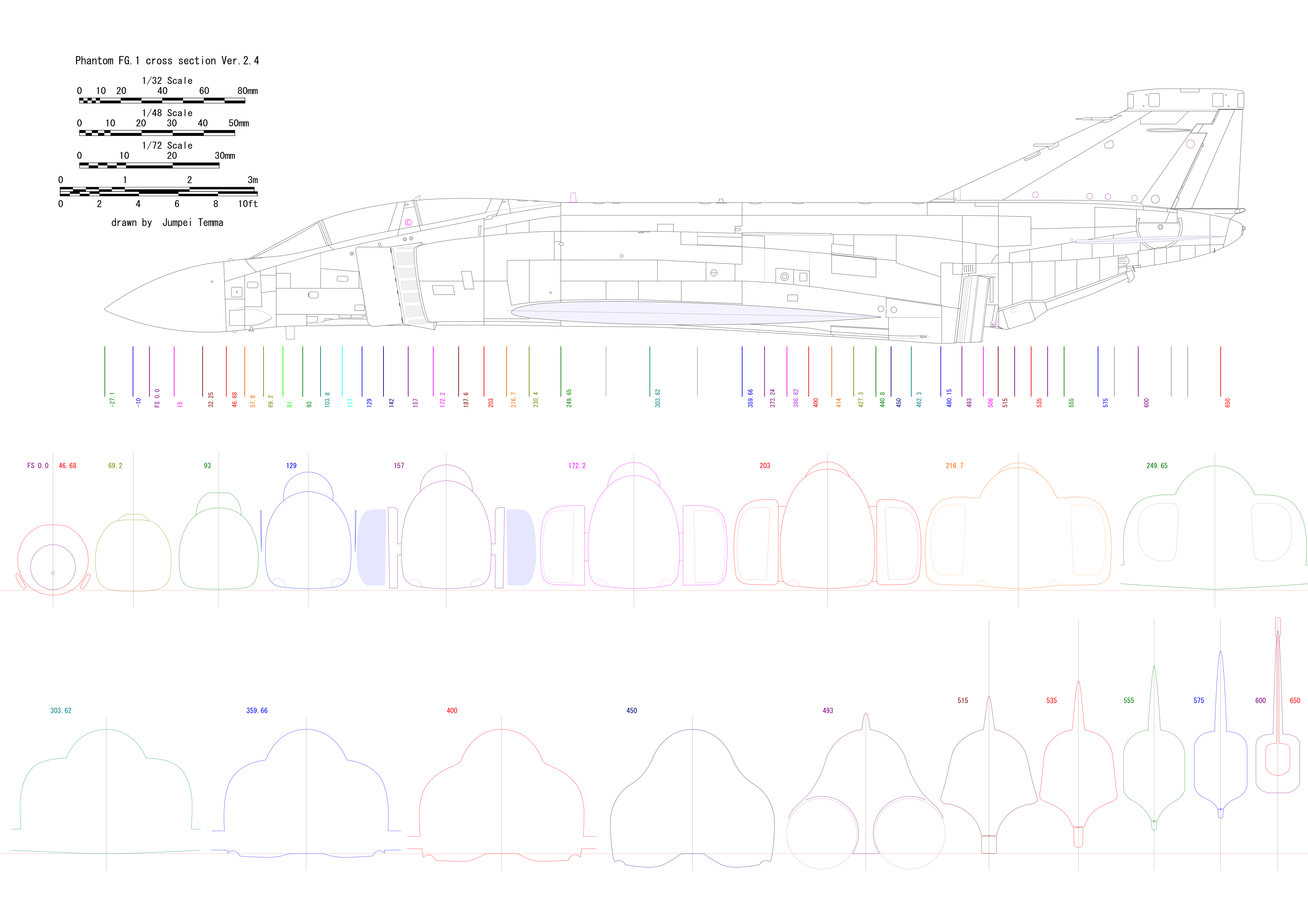
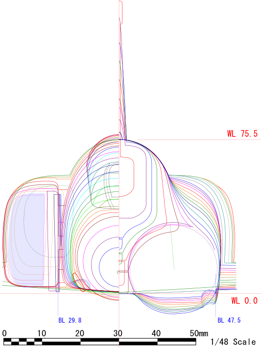
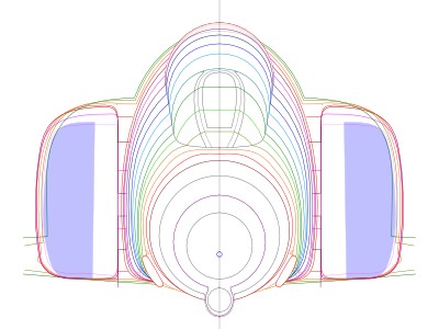
This is the cross-sectional contour view. Of course, this figure is based on factory drawings. Each color is match to my side/cross view drawings. The light blue area indicates the shape of the intake lip viewing from the front. Pay attention to the width of the aft fuselage upper part, the height of the shoulders, the fuselage width at the wing connection line, the width of the rear canopy, etc.
|
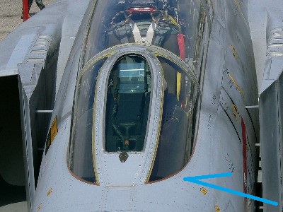
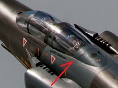
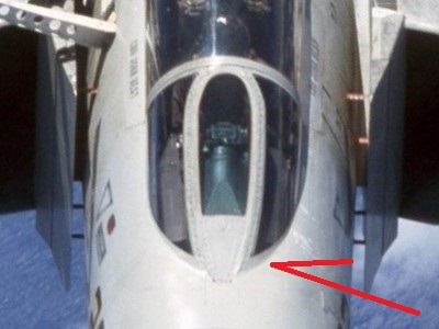 This is the short nose model. Note the opaque area (red arrow) at the bottom of the windscreen side glass. And the lower end of the front flat portion is narrow. |
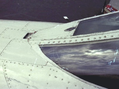
 Long nose is here. The border between the opaque and transparent areas on the left photo of the short nose becomes the fuselage boundary line of the long nose (blue arrow). The lower end of the flat portion is wide. |
 This is the short nose. The difference can also be seen by counting the number of screws on the windscreen frame. |
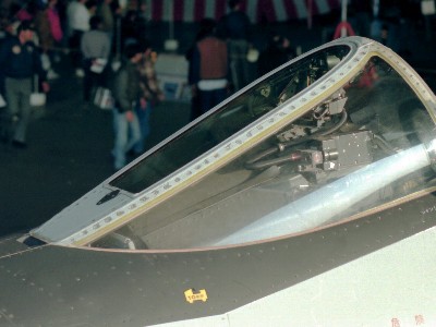 This is the long nose. The fuselage top bulges upward. |
|
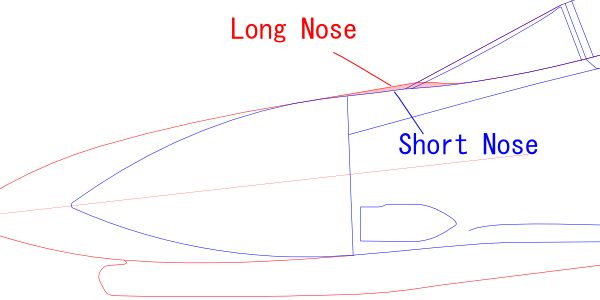
In addition, there is no opaque part as for the short nose of B/C/J models in the 1960s and the early British model but all transparent glass. The reason for this seems to be that it was initially transparent to the bottom line , and when the long nose model appeared, it was unified to with opaque glass. This is corroborated by the presence of an aircraft with and without opaque parts on the left and right. The window in the early model would have been replaced at the repair. See the following figure. Apparently, the axes of the nose cones at the tip are the same, and the long nose fuselage is not dented at the front of the windscreen. |
 |
|
I did not notice it until I made drawings. It is a shocking fact on my own. I'm afraid existing kits do not distinguish.
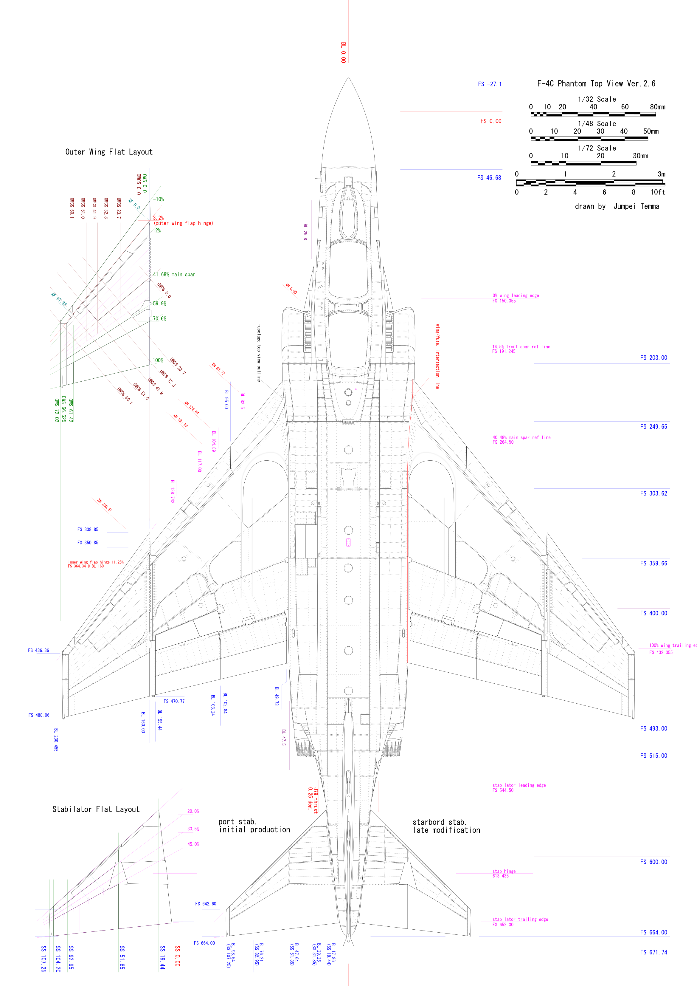
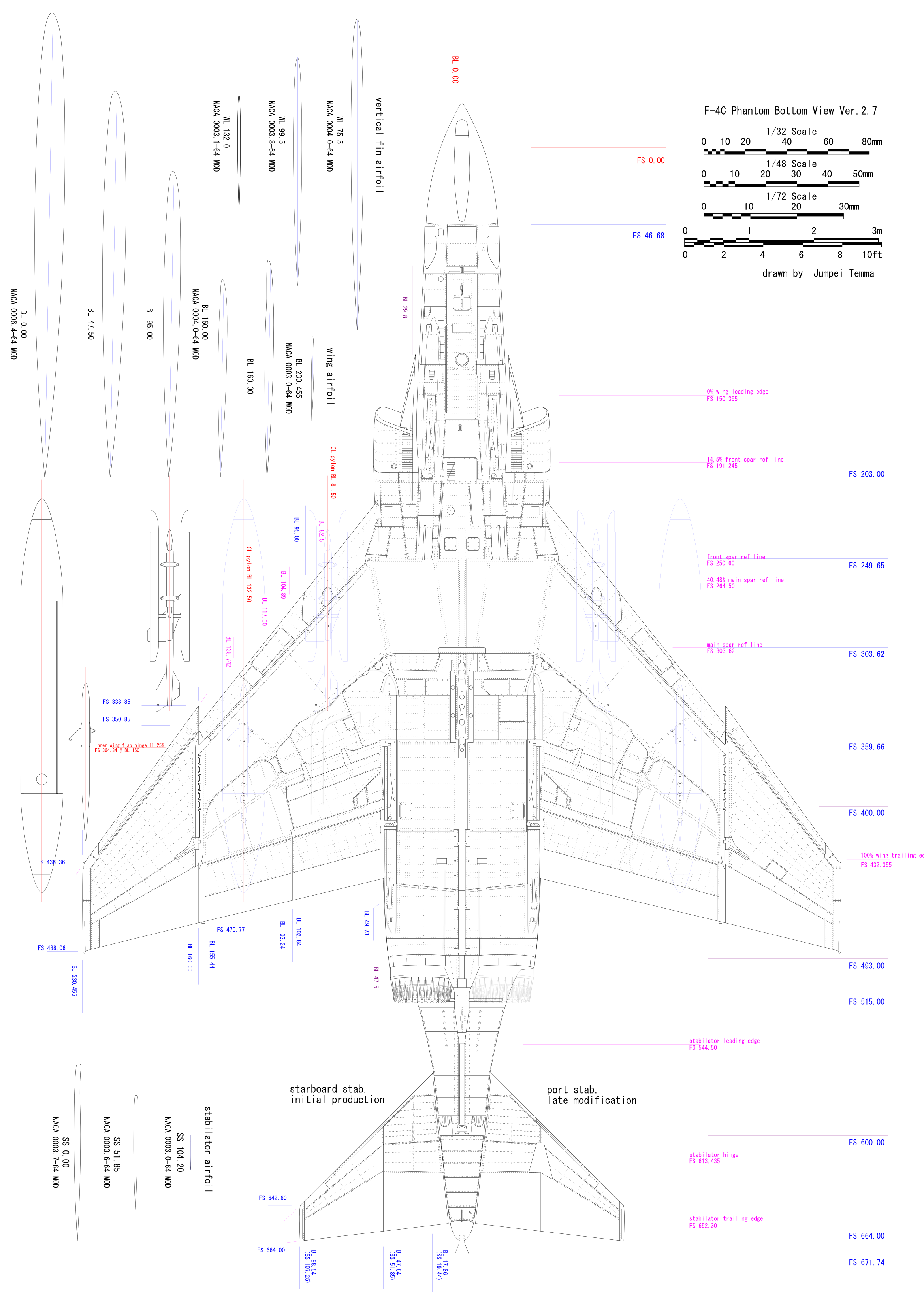
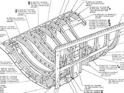
At first, the reference lines and coordinates of the wing in the factory drawings and manuals are described in my drawings as much as possible. Then I carefully determined the location of each panel line by these ref lines and coodinates. Note that panel lines do not necessarily coincide with the ref. lines. These reference lines are also complicated because there are various coordinate axes. Here, I describe each axis. FS (fuselage station) is a fuselage reference line. BL (buttock line) is orthogonal to FS and horizontal. OWS is orthogonal to FS and along the outer wing reference plane (12.0üŗ dihedral), and the origin is BL160.0. OWCS is orthogonal to the outer wing main spar (41.68% chord) and is along the outer wing reference plane. However, each numerical value is measured in FS orthogonal direction. SS is FS orthogonal along the stabilizer reference plane (23.25 üŗdihedral). Furthermore, XN is the origin of the fuselage center along the inner wing front flap hinge line (details described later). XF is along the outer wing front flap hinge line (same) with the origin BL 160.0. The WL (water line) axis is perpendicular to the ground (should it be called water surface ?).
|
 |
|
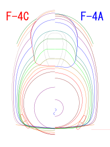
See the overlapping drawings below. The difference between the C model can be clearly understood. As for the fuselage rearward the nozzle, the shape of the upper half does not change, and only the lower unpainted metal part bulges downward. This is also unchanged after FS 555. Slits above the nozzle are the same position as the J79 model in the side view and plan view.
Next, the cross-sectional contour view lining up with C model. It's interesting to capture them and watch in a slide show.
|
 Correct top view. You may think that it is a lie, but let's look at the actual aircraft photos. Also note the difference in rear cockpit canopy. |
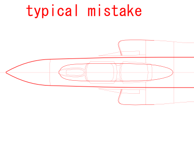 Typical mistake. Some kits (Hasegawa etc.) and drawing (FAPOTW etc.) are like this. |
|
|
 First of all, the top is FGR.2. The width at the rear seat was compared with my drawings. |
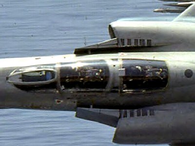
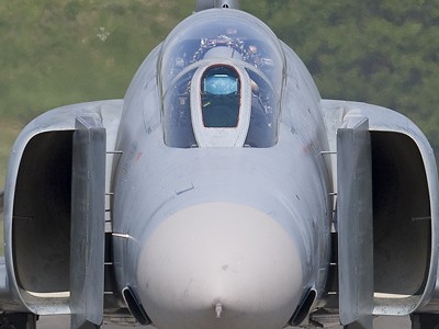
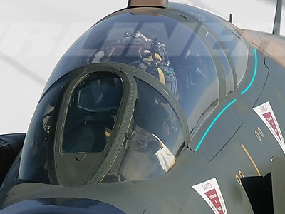
 USAF C model. The camera is a bit close, and I think the spread is weak due to parspective, but the highlight reveals the bend near the front of the rear cocpit. |
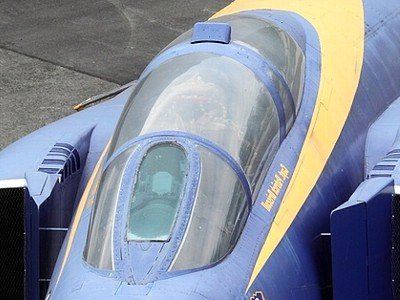 B model repainted in Blue Angels. The image is flipped horizontally. Pay attention to the S-curve (mention later) at the fuselage and canopy boundary and the parallel line of the windscreen side window. |
 Luftwaffe F model. It is taken from a very long distance, so it is close to the shape of the cross section drawings. Note the difference in width of the front and rear canopy frames, the roundness of the cockpit side, and the sense of volume. |
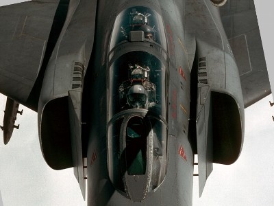
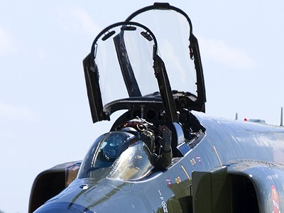 USAF E model. Even if canopies are open, the difference of the size in cross section can be seen. |
 Luftwaffe F. As for the division line with the fuselage, one more curve appeared at the rear of the rear canopy (red arrow). Mmmm.. It's so complicated. |
|
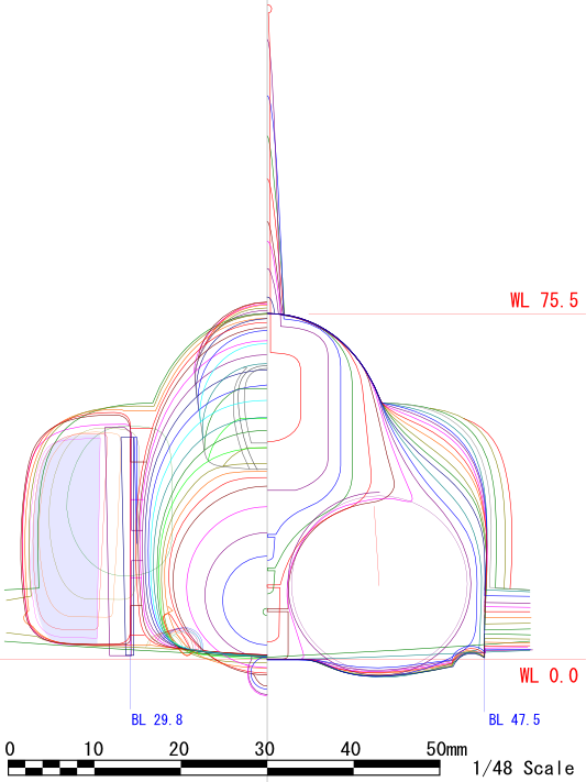
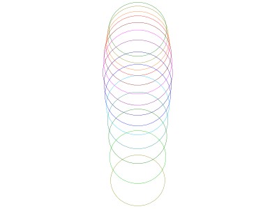
Let's check it against with the drawing. The lower left figure is the sectional view. The front end of the rear canopy is shown in pink. The lower right figure shows a circle that fits perfectly in the canopy inside. It spreads linearly and narrows linearly. |
 |
 |
|
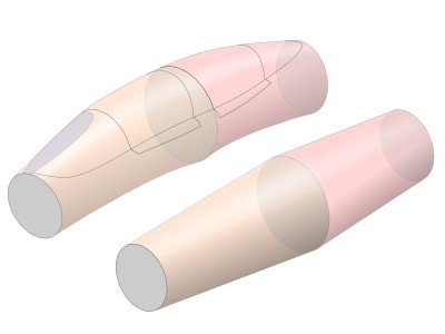
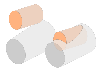
This three-dimensional model image is easy to understand if it is simplified and considered like the lower image. First of all, the basic shape is like two paper cups on the right side. An object on the left is bent so that the top line of the canopy can be curved as side view. If I chamfer the front window and draw lines of frame, it will be a very realistic atmosphere ...? |
 |
|
|
 The front seat is convex upward, and the rear seat is convex downward (light blue line). |
 Seeing from this angle, go up, go down, go up, go down and go up again. |
|
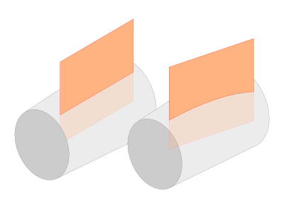
The curve convex above the front seat part can be explained if it thinks like a lower image. Assume a situation in which a tapered cylinder is cut vertically in a plane. When cut in the axial direction as in the left, the cutting line becomes straight. On the other hand, when cut diagonally to the axis, the cutting line is a convex curve (right). |
 |
|
As for the rear cockpit, the thin cylinder sinks diagonally into the thick cylinder (lower image). In this case, the roundness of the thin cylinder is excellent, and it becomes a downward convex curve. |
 |
|
|
 |
 |
|
|
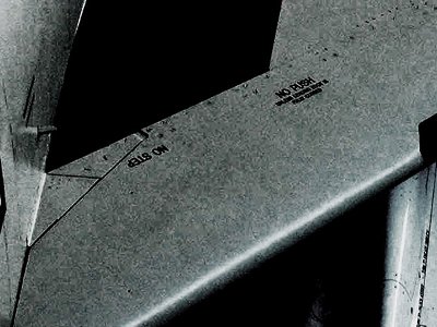
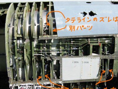 This picture shows from FS 300 to 350 on the port side. Like this, the frame itself is divided into two parts. But why is it such a design? |
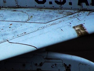
 The access door in front of the jet nozzle (opened downward by the hinge) has the same rivet lines. This figure is the port side. |
|
|
 The existing C model. |
 The existing J model. Though it's hard to see, but pays attention to the crank-shaped panel lines and arrangement of fasteners on the wing. |
 The movable type flap from the manual of A/B model. |
 The fixed type. The arrangement of the ribs is different. |
|
|