Phantom FG.1 Airfix 1/72 part 1
|
|
|
In addition, I bought a 3D printer durling this modeling. So, some insufficient detail parts will be replaced by the 3D printer parts.
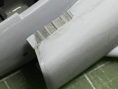
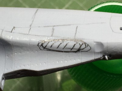
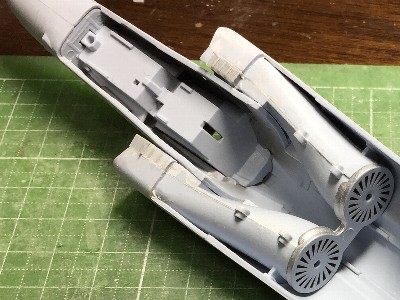
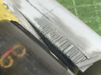
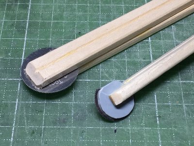
Next is the upper and lower outlet slits for boundary layer discharge. I guess that many modelers also have troubles with the work method. Initially, I tried to reproduce in engraving, but failed. Then the method of laminating plastic plates is used. 0.2 mm (.008") plate is used for each vane. The key point is to shift plate to be the vane and to be the groove by about 1mm (.04"). Thin liquid cement is used. On the way, 0.5 mm plate is appropriately sandwiched. When it is done, it happens that the number of vanes is the same as actual aircraft. One day later, it is cut in half with a rotating saw. A recess into which the laminated slit is inserted is made in the duct part. The area of the plastic plate in the groove part should be ensured so that the lamination slits do not break. The slit is glued firmly to the recess. The recess and the inner surface of the duct are very close. Therefore, it would be correct that the lamination slit is glued first when the inner duct parts are not glued to the outer duct part, and then the inner surface of the duct is sanded, and the outer duct is glued. |
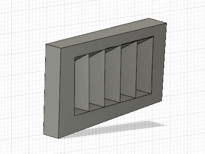
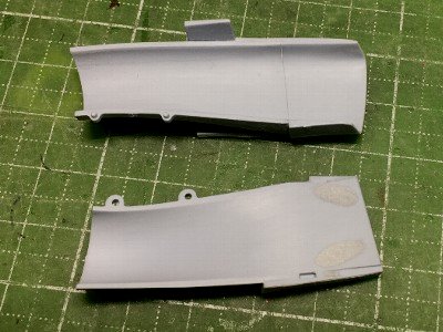 Internal and external duct parts are prepaired. Tamiya putty is used. |
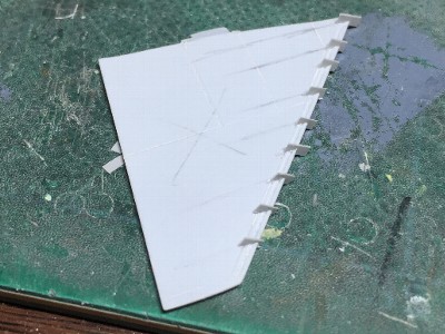
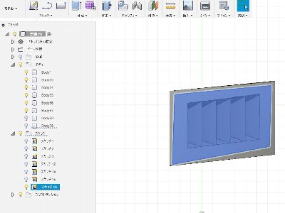
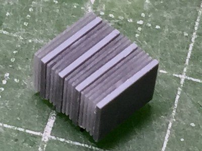 The slits are made of laminate plastic plates. Theis picture is the lower slit. Then, this is divided into two on the left and right, and the size is adjusted. |
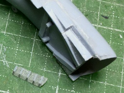 A recess is made in the duct portion and the laminated slit is adhered. CA glue should not be used, because it fills the slit. |
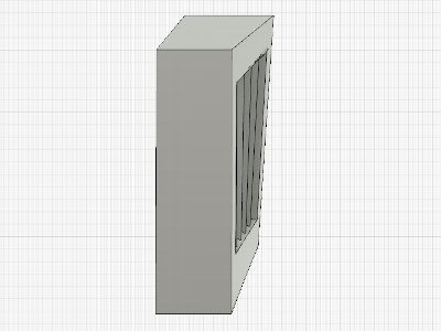
 The surfaces of the slits are slightly protruded. Then, the surface is sanded to be flat. The curved corner will be sanded later. |
|
|
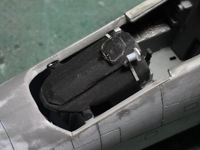
 The instrument panel on the rear seat is corrected with a knife to resemble an actual aircraft. Image is before processing. |
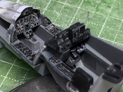 Kit decal is used. The border of the instrument is touched up in gray. |
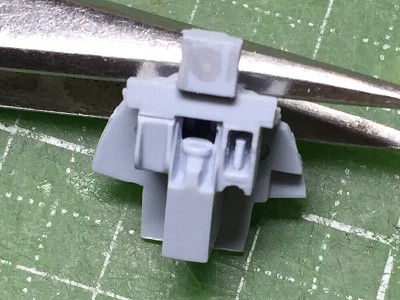
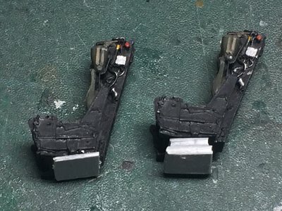
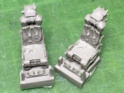 Quick boost resin seat for Phantom. |
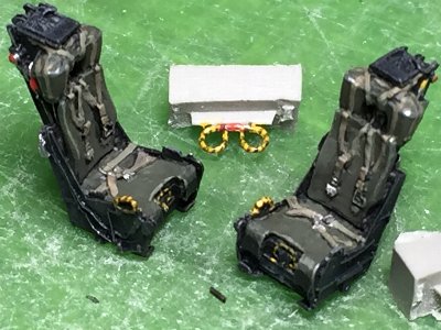 Seat cloth is painted with dark green + neutral gray. Powdery tooth paste (sorry, I don't know it is available outside Japan) is added for mat medium. |
|
|
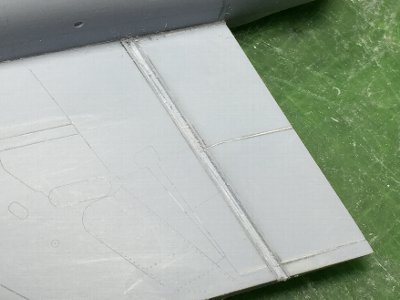
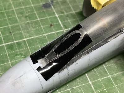
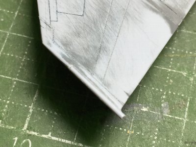
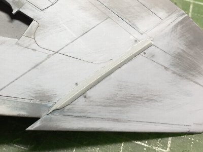
 The portion hatched with pencils is filled with CA glue + plastic powder to make the edge sharp. |
 The vertical fin base is filled with plastic plate (unwanted parts of the kit). |
 The surface is sanded starting from #180 sandpaper to #320. |
 The inside is like this. |
|
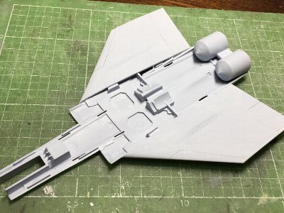
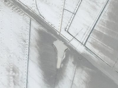
The outline shape error mentioned above is the shape of the wheel bulge. The lower side is remarkable, that is, the height of the bulge is generally insufficient. In particular, there is almost no bulge of the triangular portion between the front of the wheel cover and the main spar. In addition, the fuselage boundary on the upper surface has an odd curve around rearward of the wheel. It should be the normal airfoil without a bulge in actual aircraft. Furthermore, in the orthogonal direction, the connection of the bulge and normal wing surface is not correct. However, I do not correct these mistakes in my modeling. |
 The hard work is done. Hoo... |
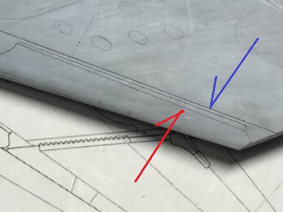 The red arrow line (filled with CA glue) is kit original frap edge line. The blue line is the correct one. |
|
After the wing is glued to the fuselage, I start engraving of panel lines. BUT, due to forceful gluing with excessive CA, filling of CA and the panel line are overlapping. For that reason, engraving can not be performed well. So, I replace CA filling at the flap and aileron hinge part with plastic. |
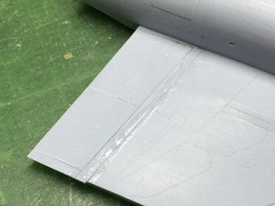 The flap and aileron are cut off and cut surfase is sanded by 2mm (.08"), and then 2mm thick plastic plate is inserted. |
 The hinge line is replaced. |
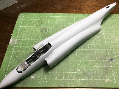
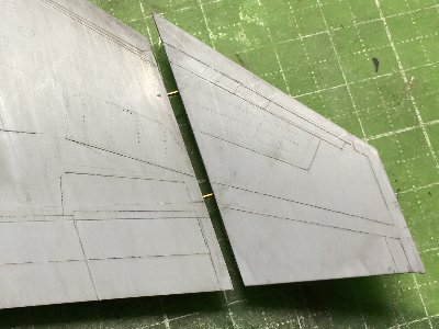 The detached outer wing is glued to the inner wing. 0.6mm brass rod is inserted for reinforcement. |
 Brass rod is also inserted in the tail fin. |
|
|
 Templates of panel lines that are not simple shapes or locations are cut with a home use cutting machine. |
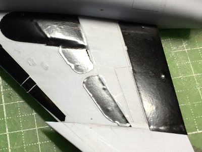
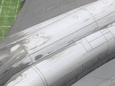
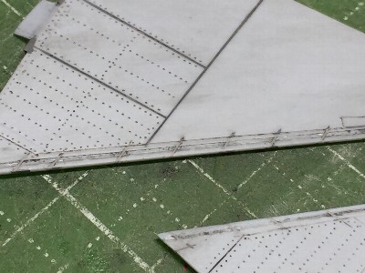
 Panel lines are finished. To confirm conditions, blue paint wash is done. |
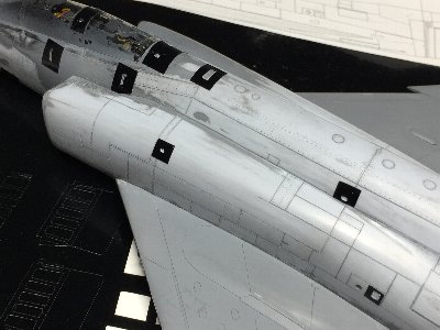
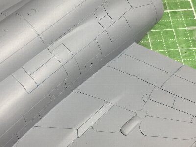 Mr. surfacer is airbrushed for confirming. The brister of the gear top is from Hasegawa kit. |
 Surfacer is sanded, then failure points are filled with surfacer by fine brush. |
|
|
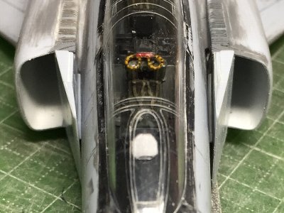
 Positions of two seats are adjusted. The front seat should be risen more 1mm (.04"). |
 HDD and instruments are added on the glare shield. |
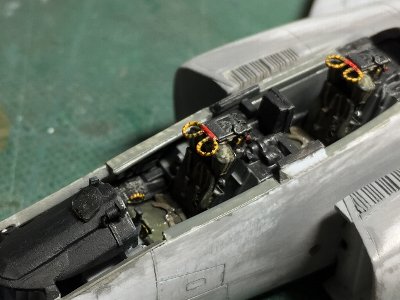 Seats are set in the cockpit. Then the canopy clear part is glued on the fuselage. |
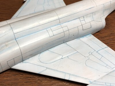
 The tenplate of the front window is cut by the cutting machine. Data for cutting is from my top view drawings. |
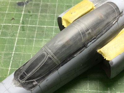 The panel line on the center of the frame is engraved with a handmade double needle using a guide of cutting sheet. |
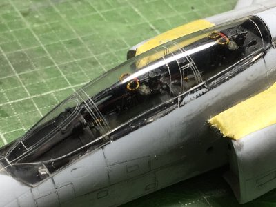 The surface is polished with rubbing compound. |
|
|
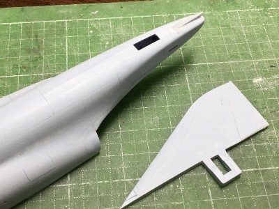
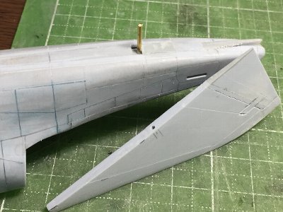
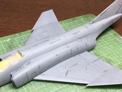
 The wing tip is replaced with extended sprue. |
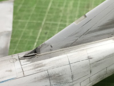 Vanes are added to the fin intake. |
 The corner of the outlet slit is sanded like this. |
 The hinge is made of plastic plate. |
 Kit's inside of the intake vane is bent. Plastic sheet is glued and sanded. |
 The starboard vane is kit original. The port is corrected one. |
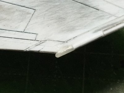 The navigation light is replaced with extended clear sprue. |
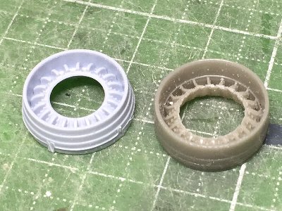 The jet nozzle is a problem. The Aires resin parts is good details but the outline is incorrect. On the other hand, the kit part is good outline dimension but poor details. |
 Some rivets are engraved with my handmade new tools. |
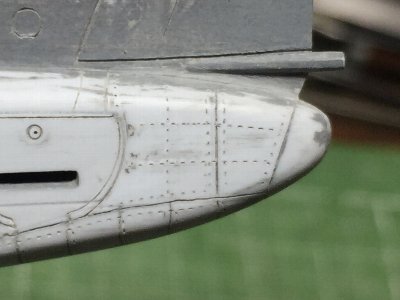 This is the result. |
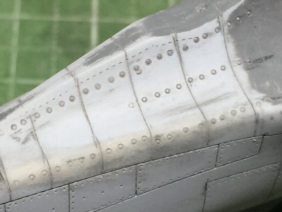 Some rivets are engraved beading tools. |
 Fasteners on the fuselage and wing are engraved. |
 Small access panel templates are cut with cutting machine. Data are from my drawings as well. It is easy. |
 Some reinforcement are made of plastic sheet. |
 I lost stabilator part. But an UK modeler sent it for me. Thank you very much. |
 0.14mm (.006") plastic sheet is inserted. |
 |
 |
 |
 |
 |
 |
 |
 |
|
|
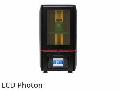 Appearance. (Anycubic HPÅj |
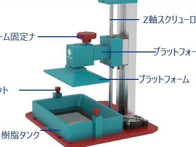 Main mechanism. (from the company manual) |
|
|
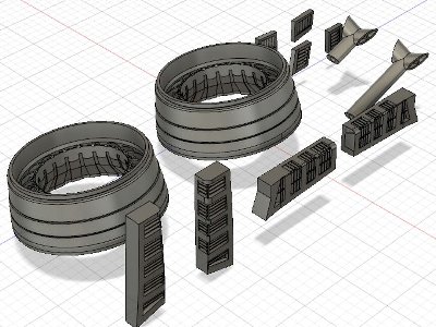
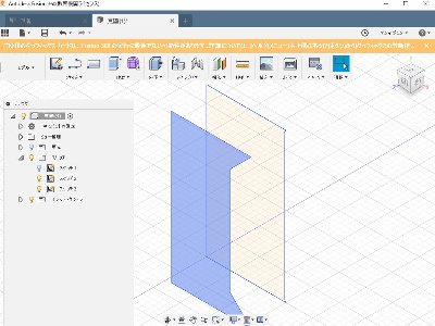
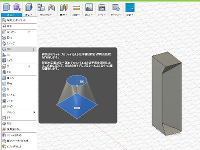
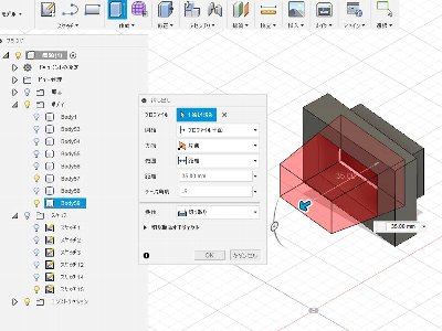
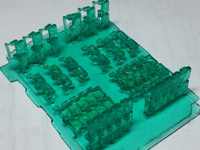
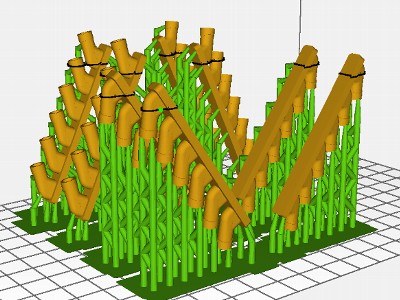 This is ready to print by the slicer. Green portions are called as supports. |
|
|
 The first work to be commemorated. |
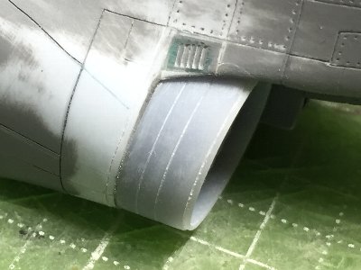
 The 3D printed slit is glued on the model. The nozzle is printed as well and is temporary set. |
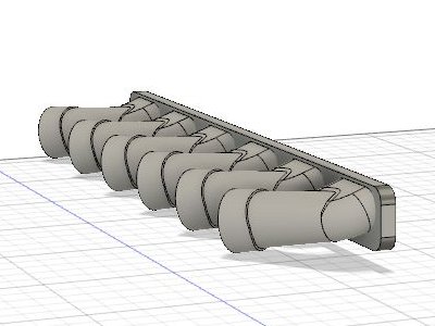
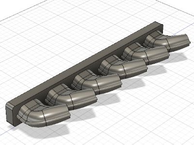
 This is 1/32 Griffon Spitfire exhaust. |
 1/48 Sherman Easy Eight track. |
 The fjet nozzle is output with gray resin and glued to the fuselage. |
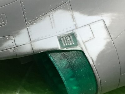
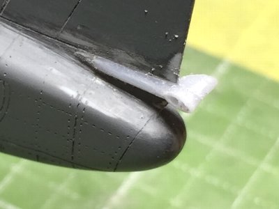 The 3D printed fuel vent is also glued t the fin. Notice that the central vane is printed. |
|
|
|
|
|
|
 |
|
1/32 Griffon Spitfire exhausÅ@data file download |
 |
|
1/48 P-40B exhaustÅ@data file download 1/72 P-40B exhaustÅ@data file download |