F6F-5 Hellcat part 4
|
|
|
|
Final detail works |
|
|
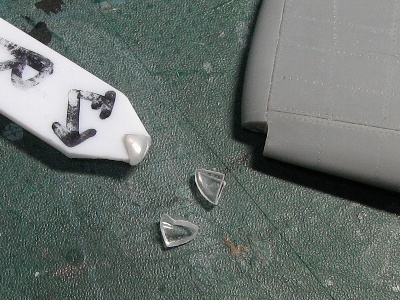
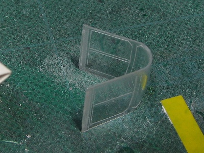
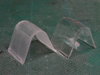 The kit canopy part is thinned with 600 grit sand paper. The right is the original kit part, the left is after sanding. |
 There is a gap between the front windscreen and the fuselage. Reason; Eduard's front fuselage is higher than the correct height by 1mm (0.04) , the kit front windscreen is a little short. |
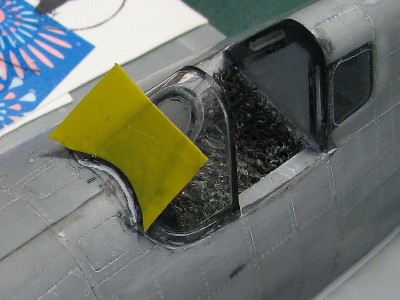
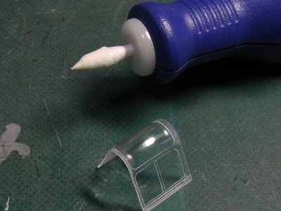
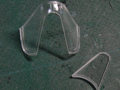 The very front of the windscreen had to be replaced. The kit part is cut with a rotary tool. The new part is from a CD case. |
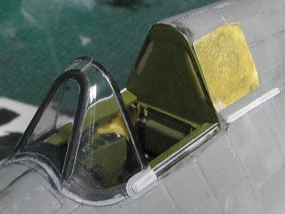
 The edge of the windscreen is painted black and is glued with Tamiya thin cement. There is no gap. |
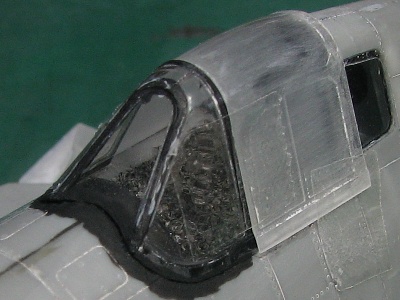 Small imperfections are filled with surfacer. Then the windscreen is glued on the fuselage with thick plastic cement (Tamiya white cap). |
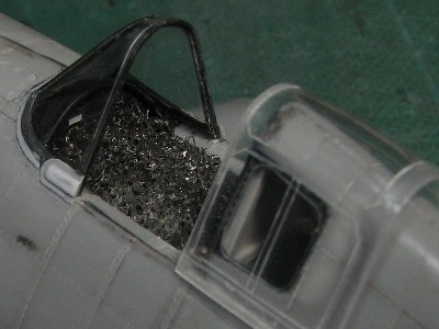
 The windscreen frame is engraved with a needle. |
 The lower fringe is from 0.14mm (.006) plastic sheet. |
 Frames are engraved with etching saw and sanded with 800 - 1200 grit sand paper and then polished with rubbing compound. |
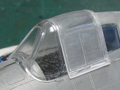
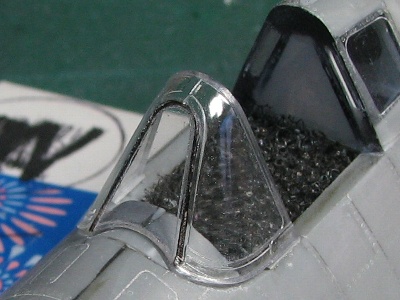
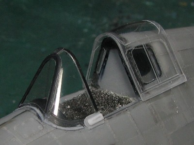 The fringe and fairing are made up. The thickness of the canopy part is thinned to the limit. |
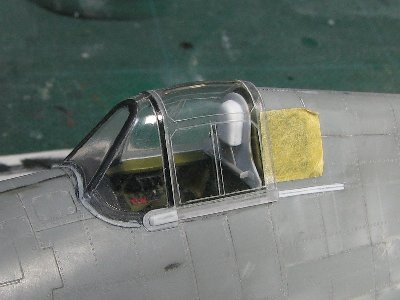
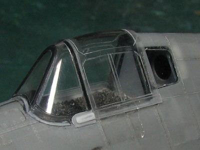 The canopy trailing edge laps over the fuselage fastback in the close position. |
 The edge of the windscreen is engraved in a step-like shape. So the visible thickness is very thin. |
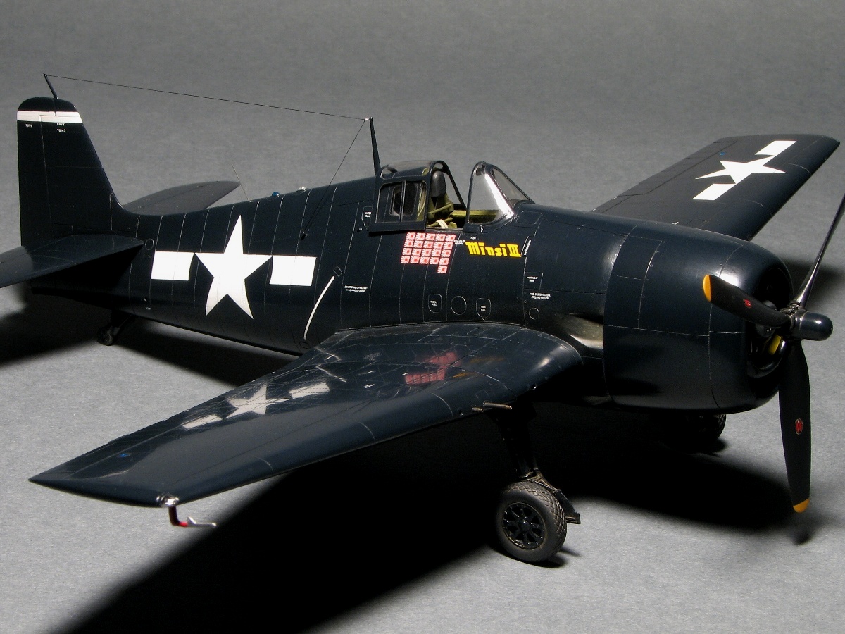
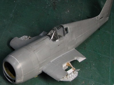 The wide and brawny body and the sharp top from windscreen thru the fastback is an essential point of the Hellcat's appearance. |
|
|
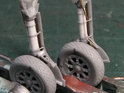
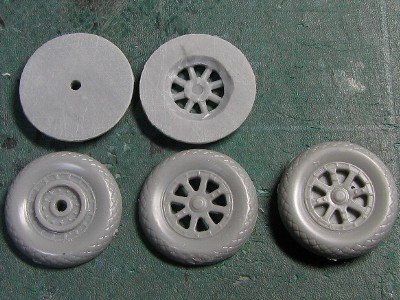 I use two sets of Hasegawa kit wheels. Each part is sanded nearly in half, then two parts are glued together. |
 The left wheel is correct. The thickness is 4.8mm (0.19) . The right is kit original with 4mm (0.16) thickness. |
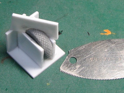 The diamond tread is engraved with thick etching saw and this jig. |
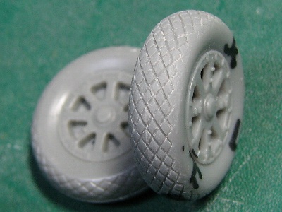 Finished. The pitch of tread is 1.0mm (0.04) and checks with the gauge of 1.0mm thick plaban. |
|
|
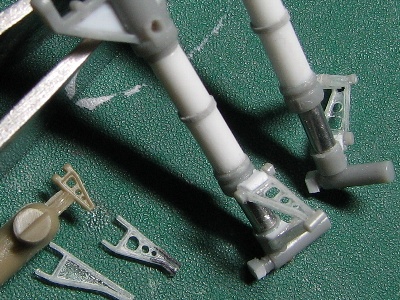
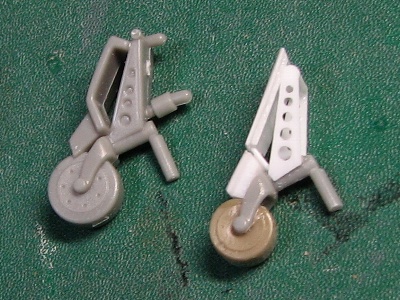
 The left has been corrected, center is Hasegawa original, and the right is Eduard. |
 The center Hasegawa part is incorrect. the oleo position is wrong. Eduard's (left) is too long; fit for "in-flight". (Who does that?) |
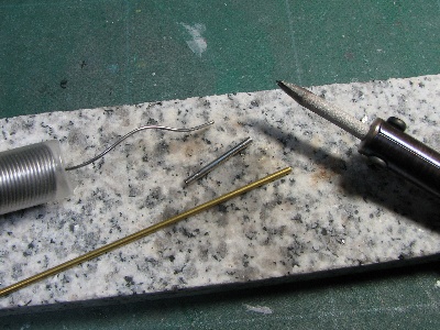 The oleo is 1.8mm (0.07) diameter. I have no suitable plated pipe. So the brass pipe is plated with solder and polished. |
 the gear leg center is drilled then 0.8mm (0.03) brass rod is inserted and glued with CA for reinforcement. |
|
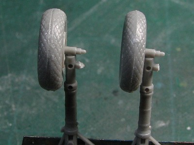
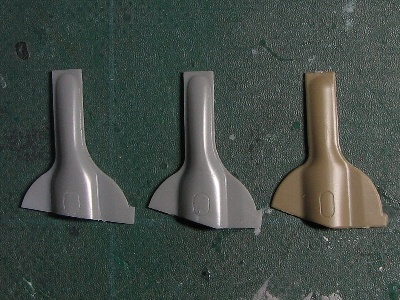
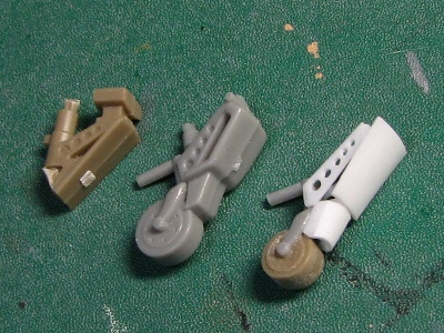
The torque link is important for Hellcat modeling and is very noticeable. The etching parts are convenient, but poor in 3-D. So I scratched built them from 0.2mm (0.008) plaban with their "H" cross section. The details such as the number of holes and shape are different between upper and lower parts. |
 Torque links are scratched built. Hinge portions are stretched sprue. Eduard's part (brown) is small and looks closer to 1/72nd scale. |
 Kit gear cover is cut off at lower portion and sanded thin. The actual gear cover is made from one sheet of metal. |
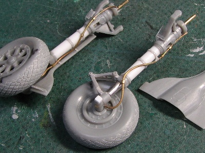 The brake line is annealed brass rod. |
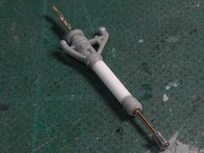
 Finally the landing gear is finished. I'm very satisfied with the look of the tire and torque link. |
|
|
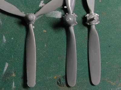
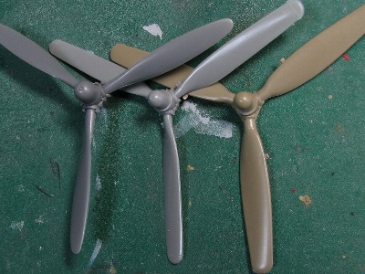 The left is the Accurate Miniature SB2C-1, center is Hasegawa, and the right is Eduard. |
 The left is Hasegawa, the center and right are Tamiya P-47D (after sanding). |
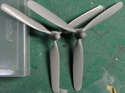 The Tamiya blades are glued to the Accurate Miniature hub on the right, the left is Hasegawa. |
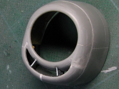 Photo-Etched mesh is used on the intake. |
|
This corrected (widened and re-shaped) propeller depicts the Hellcat's high power and performance much better!
|
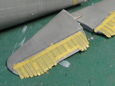 Ribs are masked with tape. Each width is equalized as much as possible. |
 Thick surfacer is applied twice with fine brush. The pencil guideline is specific skill. |
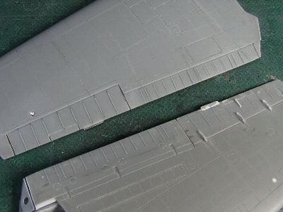 Some existing drawings made mistakes in the number of ribs depicted. Actually; the aileron has eight, the flap has fifteen (upper) and fourteen (lower), and the distance of ribs at hinge position is narrower. |
 The position of the tab is different between -3 and -5. The formation light is made of aluminum sheet and clear vinyl chloride sheet (see my F-86 page). |
|
|
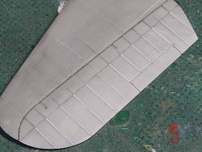
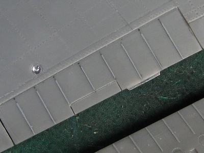
 I tried to depict the thin cover of the navigation light. The cover was heat pressing with clear 0.2mm (0.008) Tamiya plaban. |
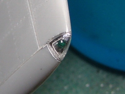 After the clear cover was glued on the wing, the surface was sanded, engraved and polished. |
|
He uses a knife in videos, but I use (and recommend to use) a rotary saw.
|
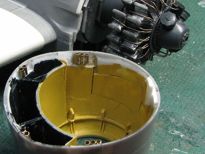
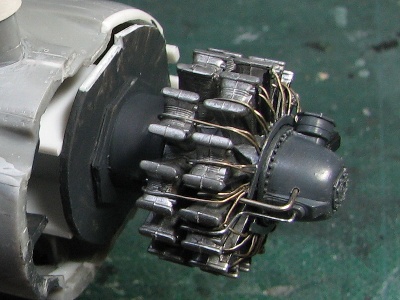 The engine is placed on the fuselage. |
 The exhaust pipe is 1.2mm (0.05) brass pipe. |
 The tail gear is almost entirely scratch built. |
 The Eduard's fork is so short that I selected the Hasegawa part. |
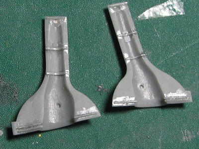
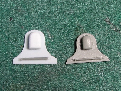 The bulletproof plate is entirely scratch built. The right is Aires resin part. It is too short in height. |
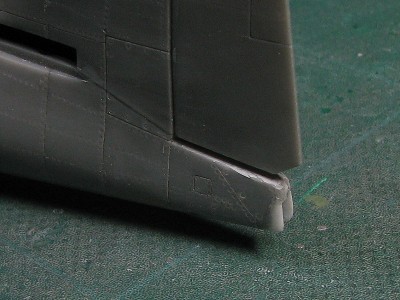 The shape of the tail end has been corrected. |
|
|
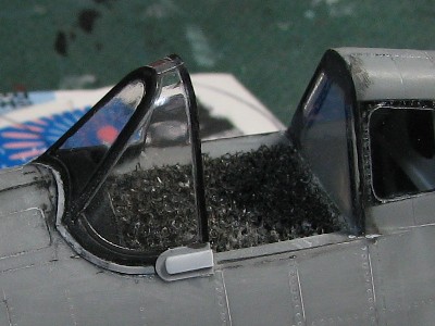
 The canopy slide rail is made of 0.3mm (0.012) plaban. 0.3mm slot was engraved on plaban with GIS Creos's "Mr. Line Chisel (0.3mm)" before cuttting out. |
 The rail, made of 0.2mm plaban is glued to the lower inside edge of the canopy. The rail clicks in place and is held in the slot of the slide. |
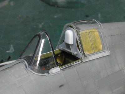 Then the canopy is installed on the fuselage. |
 It moves closed and the fit is outstanding! |
To Be Continued