F6F-5 Hellcat part 3
|
|
|
|
The wing again |
|
|
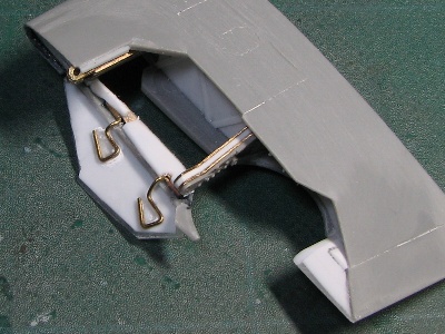
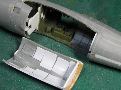
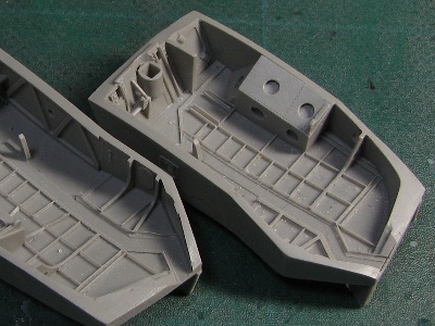 These are the Aires's resin Main Landing Gear bays. |
 At first, I made the box from 0.3mm (0.01) plaban. The box interfered while wing was folding, so by trial and error I made it fit. |
 Detailing of interior is finished. |
 The leading edge of the flap is visible from the gear bay. The landing gear is to be fixed directly onto the main spar at the hole of the brass bar. |
|
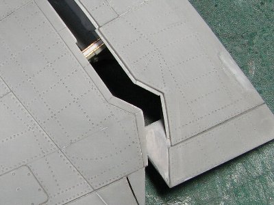
Unfortunately, I couldn't depict completely like the actual A/C. Reasons; (1) there is the wing divide line on the center of gear bay, (2) the position of the connecting member is not correct; it interfered with the wing cutting line, (3) the wing cutting line and the shape of opening of the kit were a little incorrect, (4) the thickness of the gear bay ceiling could not be thinned for riveting work. By the way; this wing cutting line is complicated but when the wing moves we can understand the necessity of each corner and line. |
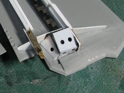
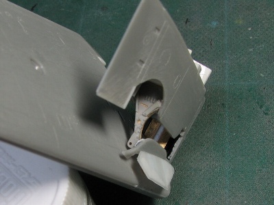
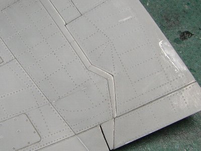
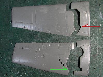 What's the meaning of the corner (red arrow)? Why this line is skew (green arrow)? |
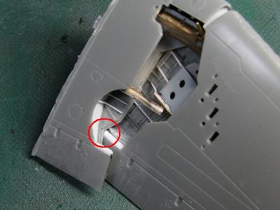 The red arrow corner is to clear the front edge corner of the flap. |
 See how tight the clearance is. |
 The clearance of the box and beam is tight as well. |
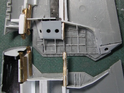
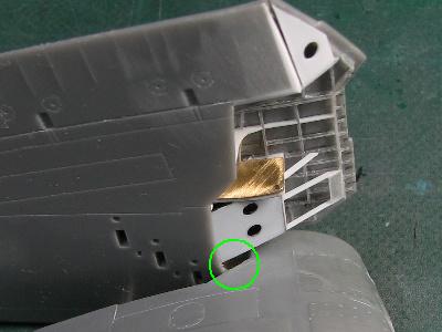 See the gap where the green circle is? |
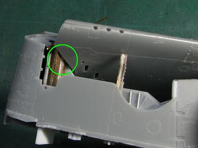 This is why the skew shape of green arrow. The skew line fits to the skew main spar web. |
|
As the gear bay was finished, the upper wing part and lower wing part were glued together. As already stated, the absolute thickness of the center wing area is constant on the actual aircraft. So the wedge shaped shim was inserted into the adhesive line of the leading edge to increase the thickness to 0.5mm (0.02) at the wing folding line.
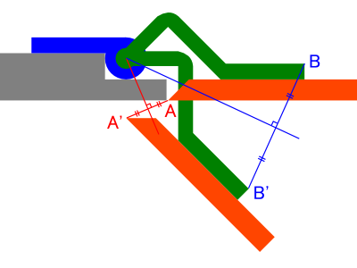
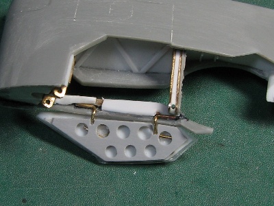
At first, I drew a rough sketch. The orange figure is the door, the gray is fixed portion, and the hinge is the combination of blue tubing and green rod. In this kind of hinge door, when point A moves to A' and point B moves to B', the vertex of the perpendicular bisector of line segment AA' and the perpendicular bisector of BB' becomes the pivot of this hinge (A and B are arbitrary). |
 |
|
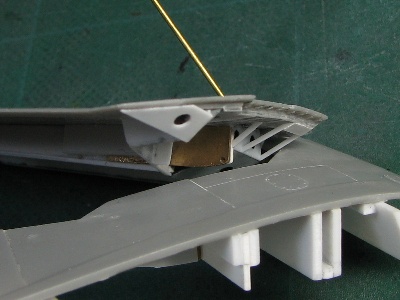
Then I started construction. And also, I found how the construction of this door was very difficult like the wing connecting member was. As you can see in the sketch, the pivot is a little inward from the cutting line. Therefore the green rod has to be bent to clear the edge. However, the thickness of the bent rod is limited while wing is folding. |
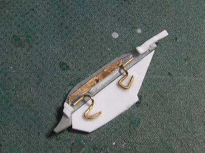 0.7mm (0.03) brass tubing is soldered to thin brass sheet. The stay is 0.5mm (0.02) brass rod. The door is 0.5mm plaban. Errors are let loose into the gap between the door and stay. |
 The fixed portion is glued to the inner wing at only two points. These small adhesive points get lots of stress with door moving, so the adhesive had to be rigid. |
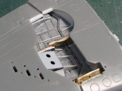
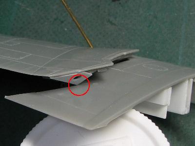
 The clearance between outer wing and door hinge is very tight. |
 The adjustment of the pivot position, curve of brass rod and adhesive point of fixed portion etc. is very delicate. So I remade it several times. |
|
There is a perforated plate on the inside of the door. I cut this plate from 0.14mm (0.006) plastic sheet with my home use cutting machine "Craft Robo CC330-20". I normally use Craft Robo for masking sheet cutting (see my page of Panzer III, Sherman VC, Spitfire PR.XIX etc.). |
 This is the Craft Robo CC330-20. It can cut A4 size sheet. The price is only \20,000 (250 USD). I strongly recommend it for senior class modelers. |
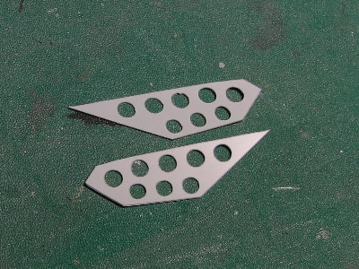 This part is cut with the Craft Robo. |
 It is glued on the door. |
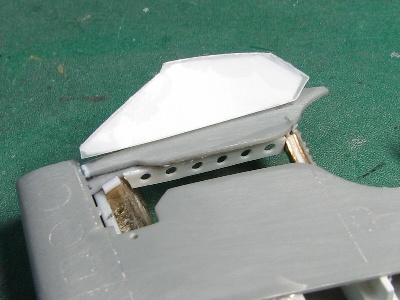 0.2mm (0.009) clear plaban is glued on the outside. |
|
I devised the mechanism for the door in the closed position. But, the door can be fixed with the friction between the pipe and rod. So I tentatively left them.
|
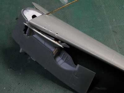
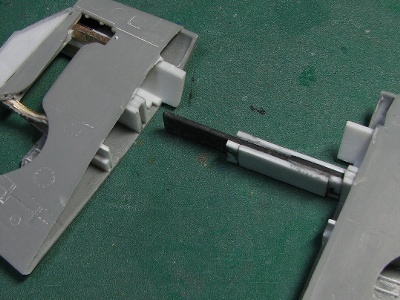 The left and right wings are connected with black carbon fiber material (not for sale). |
 The mortise joint structure must be precise and rigid. Reson; this structure supports the stress of each wing. |
 The lower fuselage is detachable for a while. Epoxy putty was put on the rear joint. This putty keeps the lower fuselage in the correct position. |
 The front end of the lower fuselage is fixed with 1.2mm plaban ( 0.05 plastic sheet). |
 The height of the center fuselage is checked against my drawings. |
 The wing position is carefully adjusted and is not glued yet. |
|
|
The Horizontal Stabilizer |
|
It is thought that the left and right horizontal stabilizer are interchangeable, but if you look closely, you can see the upper and lower fuselage join lines are different. I think most of the parts of the fin are interchangeable, but the panel where the join line is, is different. While I was checking photos of existing A/C, I noticed some aircraft has the panel line which has not been described in existing drawings along the leading edge. But some aircraft may not have this panel line judging from photos. I think there are three possibilities. (1) Some photos may not show the panel line, but all A/C have the line. (2) There are actually two types for actual A/C (those with, those without). (3) This panel line is added at restoration or repair. I don't know which is the right answer, But most likely it may be (3). What do you think? |
 This F6F-3 has the panel line along the leading edge. This line exists port lower fin as well. So there is no possibility that this line only exists one side. |
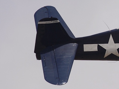 I can see the line. |
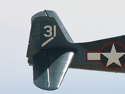 I cannot see the line. Can you see? |
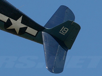 There is no line as well. (The highlight line along the leading edge may be the reflect of vertical fin.) |
|
Anyway, I started construction without the panel line. |
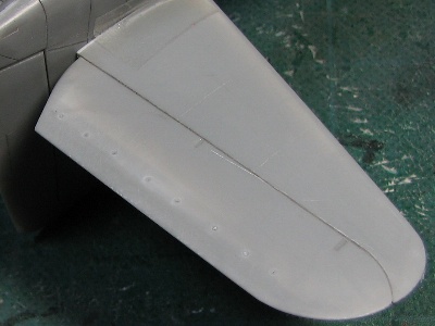 The airfoil is corrected. Plaban is glued on the inside of kit parts for the thickness of parts is thin. |
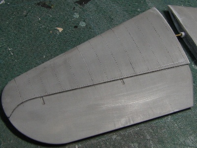 Panel lines and rivets are finished. |
|
Here I attach the station number of horizontal fin (upper) and elevator (lower). |
|
|
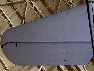
The surface detailing |
|
|
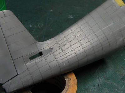 The pitch of stringers is not equivalent. I took care for the linearity of stringers. |
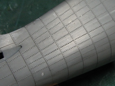 To be exact, the pitch and size of rivets are different between frame and stringer in actual A/C, but I didn't depict this. |
|
There may be a minor difference in the arrangement of stringers in some A/C (early -3 model ?). But I couldn't figure that out yet. Anyway, I tried to depict the normal -5 arrangement.
The panel & rivet lines in existing drawings are not correct either. I checked the wing station number and actual A/C photos, then I figured out the correct panel & rivet lines as much as possible. See following pics of my model. There are some remarks below.
|
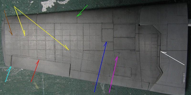 The trailing edge of fixed wing should be move backward by 1 to 2 mm (0.04 - .08 )(red). The span of the aileron is enlarged 1mm (aqua). The panel line is on this rib (same as -3 model) (green). Some existing drawings show panel lines on these stringers, but they are not confirmed on actual A/C (yellow). This panel line is moved forward 1mm (blue). Kit access panel interferes with rivet line, so this panel is reduced (magenta). This wing divide line is straight and no crank in actual A/C. Well, I know I didn't correct it (white). Only this rib is bent at this point and reaches to aileron side (brown). |
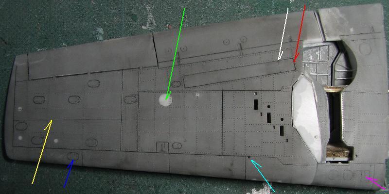 The long box access panel forward of the flap in lower side is better if enlarged by 5mm (0.2) toward the fuselage (white -> red). The hole of the port landing light must be filled in. Only -3 model has this type of light (green). This panel line is not confirmed on -5 model (-3 model has it?) (yellow). Small ellipsoidal access panel is added here and locations of other panels are adjusted (blue). This square access panel is port only (magenta). This small hole is for connecting the outer wing with a pin at folding (aqua). Basically, port and starboard wing are identical unless a special note is added. |
|
|
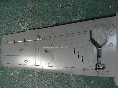
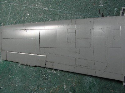 These are the kits original wings however, the kit basically depicts -3; so panel lines are quite different. |
 |
|
|
 The fringe is added with 0.14mm (0.006) plastic sheet. |
 The actual A/C has no step like my model. Thin metal plates of outer and inner wing simply overlap; but it couldn't be depicted in 1/48th scale by me. |
|
|
Assemble the wing and fuselage |
|
|
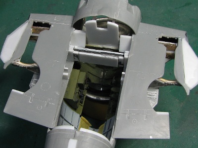
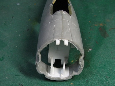
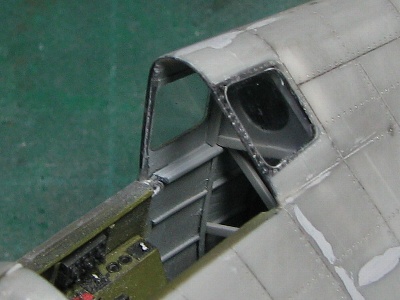
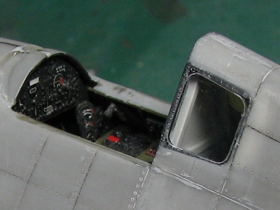
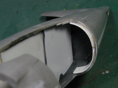
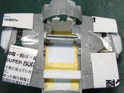
 The interior is finished.; then will be completely sealed up to protect from dust or overspray from paint. |
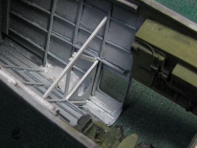
 Notice the triangle bulkhead with the large circular hole. |
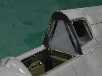 The bulkhead is 0.4mm (0.016) clear plaban. There are narrow windows at the sides. I guess the windows were useless and they deleted them after mid -5 model. |
 The frame is added to the backside, then the cockpit floor is glued to the fuselage part. |
 This floor and bulkhead (it may hardly be seen) seal the interior portion. Of course, they don't exist in the actual A/C. So the floor is painted dark gray. |
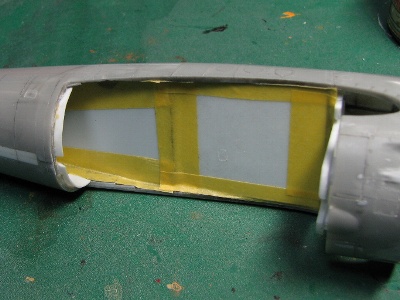 And tape is applied to seal it as previously explained. Now dust and overspray should be eliminated from entering. |
|
|
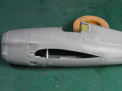
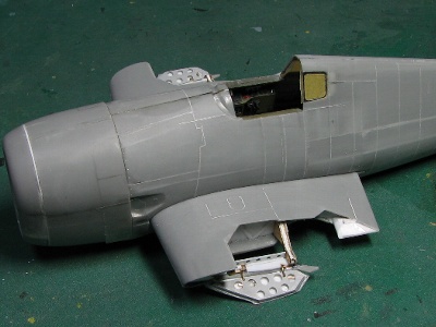
 At first, left and right wings are assembled and then the assembled wing is glued to the fuselage. |
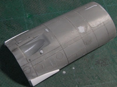 The -5 model has these triangle fairings. |
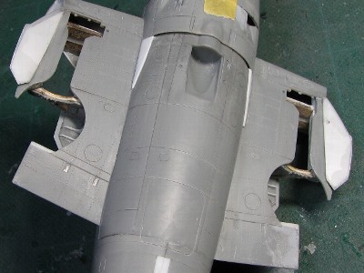 The lower fuselage is glued to the upper portion; panel lines and rivets are engraved. |
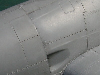 Fasteners are engraved with #5 beading tool. |
|
|
To Be Continued