F6F-5 Hellcat part 2
|
|
|
|
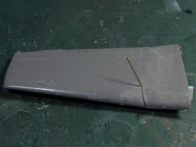
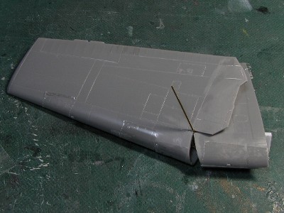
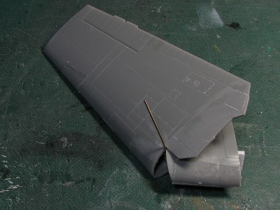
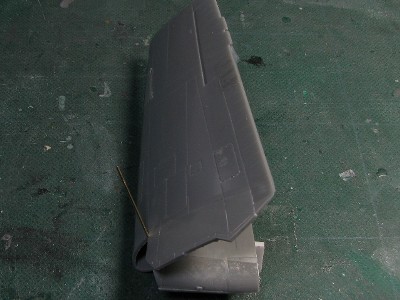
The wing |
|
|
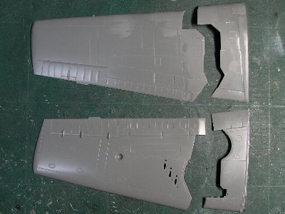 The wing is cut with a craft knife. |
|
Therefore, I proceeded to calculated the angle of axis with a mathematical approach. See the following figures. The left figure shows the port wing in the three-quarter view. The x-axis is along the wing span, the y-axis is the plane axis, the z-axis is the vertical direction and the origin is the rotation axis.
Point P moves to Q and point R moves to S with wing folding. At this time, point P, Q are on the plane I, which is perpendicular to the rotation axis, and point R & S are similarly on the plane II which is perpendicular to the axis. The position of P to Q when wing is folding becomes an arc, and plane I & II are parallel to one another. The mathematical formula of a plane is written as (1). a x + b y + c z + d = 0 ----(1) At this time, a, b and c express the slope of the plane. And the vector (a, b, c) is perpendicular to the plane. So when we set up values of a, b, and c; we can find the angle of the axis. Now, let us remember the characteristics of the plane. If two planes are parallel, values of a, b, and c in formula (1) are equivalent each other, and only the value of intercept term d is different. Therefore, when we substitute each coordinate of point P, Q, R & S into the equation (1), we can get following simultaneous equations (2) to (5). a x1 + b y1 + c z1 + d = 0 ----(2) a x2 + b y2 + c z2 + d = 0 ----(3) a x3 + b y3 + c z3 + d' = 0 ----(4) a x4 + b y4 + c z4 + d' = 0 ----(5) At this time, variables are; a, b, c, d and d'. The answer which we seek is the ratio of a, b, c. So, at first, we set a = 1. Next, we eliminate d & d'. Then we finally get values of b and c as follows. b = {(x1-x2)(z3-z4)-(x3-x4)(z1-z2)}/{(y3-y4)(z1-z2)-(y1-y2)(z3-z4)} c = {(x1-x2)(y3-y4)-(x3-x4)(y1-y2)}/{(y1-y2)(z3-z4)-(y3-y4)(z1-z2)} Values of coordinates x1, x2, , , , , z3, z4 may be obtained by measuring on the actual model. Calculation of b and c is comparatively easy when we use an Excel sheet.
Æx=tan-1(a/c) Æy=tan-1(b/c) Well, let us calculate the actual 1/48th model. The wing span in folding position is 65mm (2.54") and the height of the wing tip from upper wing surface is about 30mm (1.2") in 1/48th scale. The angle of wing slope in folding position is about 55, dihedral is 7.5. This data was input to Excel, finally I get a solution that; Æx = 28.5 and Æy = 26.3. As for modeling, the projection angle of the plane of main spar web (Æw) is useful. At this time, here is following formula. tanÆw = cosÆy * tanÆx = a/(b^2+c^2)^0.5 Then Æw is 25.9.
Thus, I found that "Model Airplane News" drawings are correct. Was it a waste of time? Yes, it probably was but I was able to verify that what they drew is accurate and this calculation method can be used for not only the Hellcat but for the Wildcat, Avenger and even Fairey Firefly.
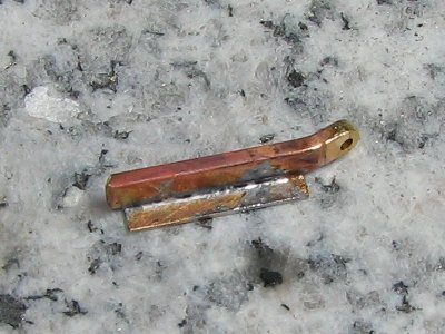
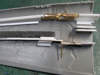
At first, the basic structure of hinge was assembled. That is; the axis of brass rod was run through drilled four brass square bars. Of cause, the angle of brass rod was critical. Then the outer and inner main spars were glued on brass bars by epoxy glue. This is artifice 1. |
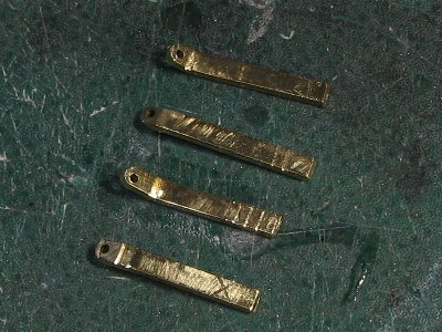 1mm X 2mm (0.04 X 0.08) brass square bar is used for the hinge member. Then 0.8mm (0.03) holes for the axis were drilled. Then the brass bars were bent to the accurate angle. |
 This is the pocket burner "Pocke Torch". It is useful for cooking as well according to the manual. How about for "aburi sushi?" |
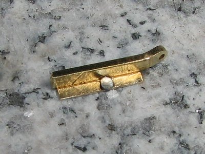 Solder is cut into a small chip + flux is used. The base I soldered on is small stone slab. |
 Then the parts are heated with the Pocke Torch. |
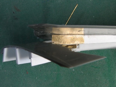
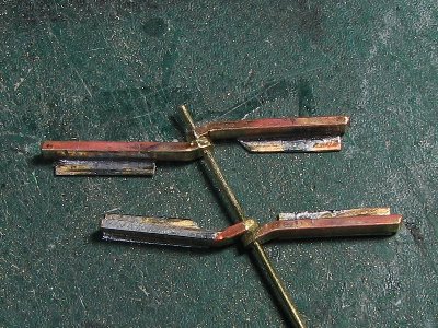 Resembles a dragonfly, yes? The basic structure of the hinge is finished. This is for starboard and the right side is for the inner wing.. |
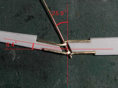 The main spars of 1.2mm (0.05) thick plastic are glued onto the dragonfly. The lean angle of hinge axis is 25.9. According to my calculation, the projection dihedral of the spar web plane is 8.4. |
|
Errors ( the positions or angles of drilled holes, or bent angles etc.) were let loose into adhesion gaps. That is; errors of hole position or hole angle caused by hand drilling are unavoidable. But if the adhesive portion between brass bar and spar of white plastic allows a small gap filled with glue, the precision of the hinge alignment is maintained. And if the bar and spar are tightly glued without gap, precision of the hinge is not ensured. Next, upper inner wing and outer wing parts were accurately connected by Scotch tape taking care to keep the correct dihedral. Then the completed hinge and spar section was glued on the connected wing parts giving care to the angle of the spar web. Errors were let loose into adhesion gaps as well. The lower wing parts were glued at the end. This is artifice 2. |
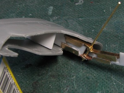 Everything is dry fitted. The spar leans backward by 26.3. |
 Movement is checked before gluing. |
 |
 |
 |
 |
|
The details of the hinge were different from actual A/C as you can see, but that is the limitation in 1/48th scale.
|
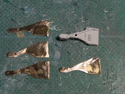 The inner connecting member is made of 0.3mm (0.01) brass sheet. The upper right is Aires's resin detail part. |
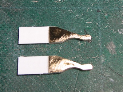 The brass parts were glued on 0.8mm (0.03) plastic with epoxy glue. |
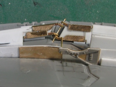 Each connecting member is drilled with 0.7mm (0.03) holes and 0.7mm brass rod is inserted. |
 At first, the inner and outer wing parts are put together with scotch tape. Then the main spar was glued. After that, the sub spars are adjusted and glued. |
|
Why this was so difficult? The clearances of these connecting members and wing cutting lines were very delicate. In other word, the cutting lines of the actual A/C were designed to clear obstacles with minimum clearance. However, the size of the connecting member could not be replicated to the correct scale to achieve adequate rigity. Therefore, connecting members would not clear the wing cutting line without delicate adjustments on the model. Thus, the position (high and low, right and left, back and forth) of members and the shape of cutting line were determined after three or four bouts of trial and error. |
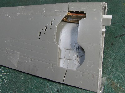
 See how delicate it is. This is the starboard upper wing. The brass sheet of the connecting member almost hits the wing edge. |
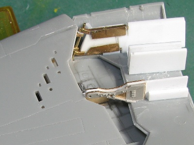 The inner connecting member clears the corner of cutting line of outer wing with razor-thin clearance. |
|
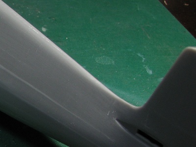
The next problem was the upper dividing line. The outer wing twisted at very shallow angles (see following pics). So the leading edge of the divide line should be very thin, and therefore; it's difficult to duplicate the accuracy for a scale model. |
|
|
See the edge of the outer wing near the brass rod. |
|
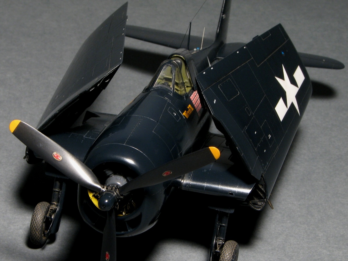
Anyway, I finished both wing folds! |
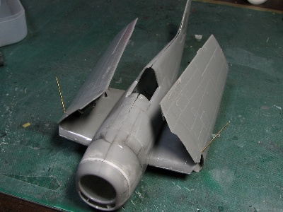 Both wings are folded. I put extra effort into the angle of rotation axis. So the folding positions of both wings are symmetrical. |
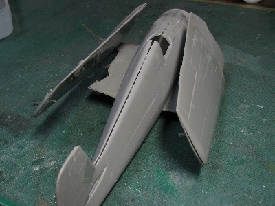 The outer wing is securely fixed with a pin through the connecting member. This is the same mechanism as actual A/C. |
|
|
| wing span | 42ft10in |
| wing span with folding | 16ft2in |
| airfoil | NACA23000 series |
| chord thickness ratio (root: fuselage center) | 14.65% |
| chord thickness ratio (tip: sta.252) | 9% |
| chord (root: fuselage center) | 10ft7in |
| chord (tip: sta.252) | 5ft3in |
| angle of incidence | 0 |
| washout | 0 |
| dihedral | inner wing : 0outer wing : 7.5 |
| span of the horizontal fin | 16ft6in |
| angle of incidence of horizontal fin | 1.5 |
| off set of vertical fin | 0 |
| wing thickness ratio of tail fins | 11% |
|
Note The thickness ratios of tailfins (both horizontal and vertical) are readout from the figure of NACA research papers. |
|
|
The fuselage continued |
|
|
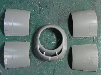 The new cowl side and originally transformed front piece. |
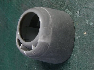 It's finished. The outer perimeter of the cowl end is enlarged by 6mm! (0.24) in total. |
|
|
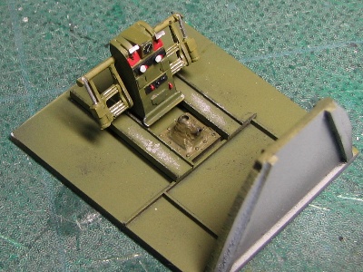
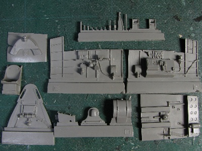 This is Aires's resin cockpit set for F6F-3. Photo-etched parts not shown. |
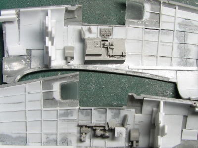 Each instrument box is cut from its sidewall backing and glued to previously reinforcement inner fuselage sidewalls.. |
 The rear quarter window is made from a CD case. |
 Aires's cockpit set is accurate and expressive. Notice the crisp molding from Aires. |
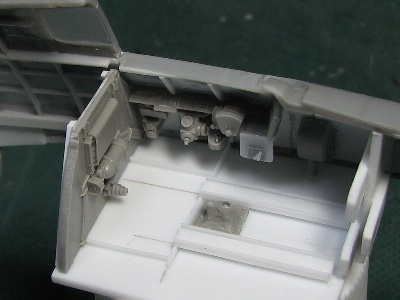
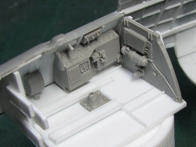
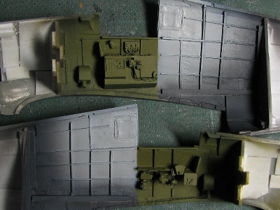 The cockpit is painted interior green. The rear fuselage is light gray. I didn't know the exact color, but I used Mr. color #338 FS36495. |
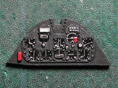 The main instrument panel is from the kit. Each instrument is kit decal punched out with punch & die then applied with Future floor wax. |
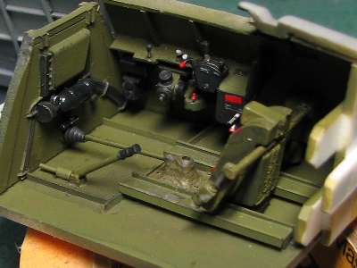
 The center console, pedals and control stick base are all from Aires. |
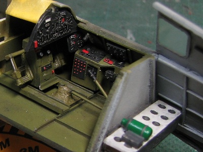 The side wall and side console of late (very late?) -5 model seem to be painted in black like as with post war Corsairs. I think that was in the transitional period to all in black cockpit same as early jets were. |
 I added some levers on the left console. |
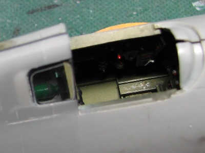 The rear fuselage area is hardly seen. Notice the green oxygen bottle. |
|
After that, the shape of fuselage was brushed up. The surfaces of cowl and front fuselage are jointed not smoothly but in broken lines as I described in my side view and plan drawings. |
 The upper ridge is sharpened. This is an important point for depicting the Hellcat's sharpness. |
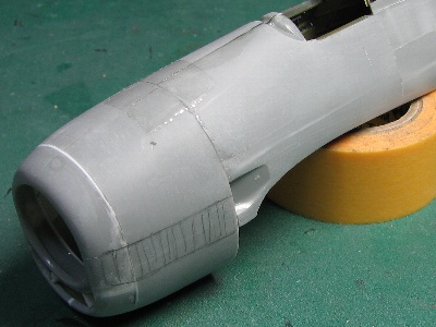 The hatching area is a quadric surface (straight line in cross section). |
|
|
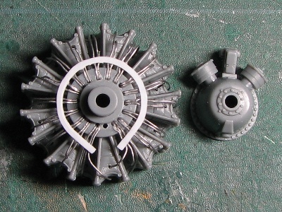 The Double Wasp R-2800-10W engine is from the Tamiya P-47. The Tamiya Double Wasp is very well detailed but a little under-scale in diameter. |
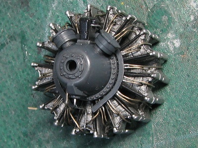 The gear housing is painted with extra dark sea gray. Plug harnesses are 0.3mm (0.01) solder wire. |
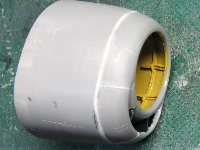 The inside of F6F-5 cowling is painted Zinc Chromate Yellow. So details are easily istinguished. |
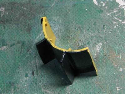 The partition between the engine and intake duct is not correctly depicted, but may be poorly-visible. |
|
|
To Be Continued