F-86F-30 Sabre (Hasegawa 1:48) part 1
Jan. 2011
|
|
Great thanks to Mr. Mario for checking my English text!!
|
|
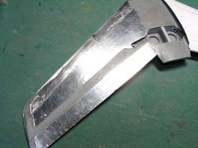
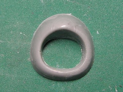 The edge of the intake lip was thinned (the port side) to compensate for 0.3mm thickness of aluminum. |
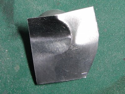 The actual aircraft's part consisted of three main panels, so will the model. To begin the annealed 0.3mm alu sheet is pressed on the lip edge. |
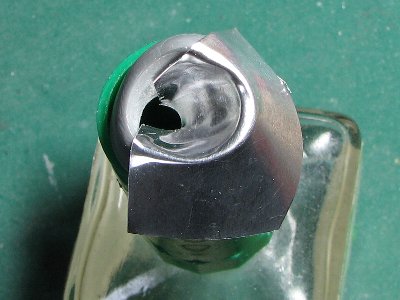 Then the sheet is folded to inside and outside with some rounded sticks (for example the rod of brush). |
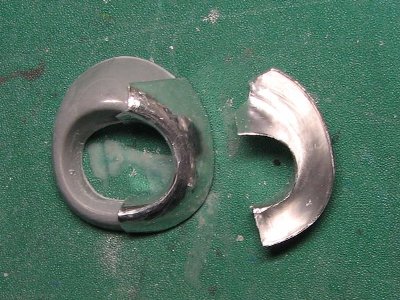 The port and starboard side lip panels are finished. |
|
|
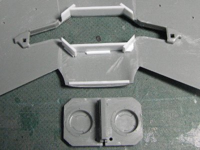
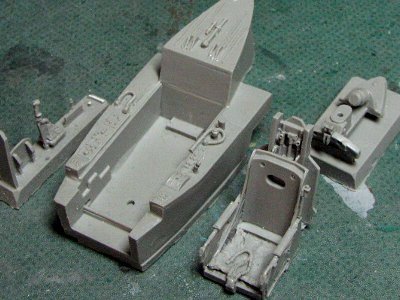 This is Aires's resin detail set. I don't use the side console and floor parts. |
 The kit cockpit floor is extended with plastic sheet for the fuselage reinforcement. The side consoles and bulkhead are added. |
|
|
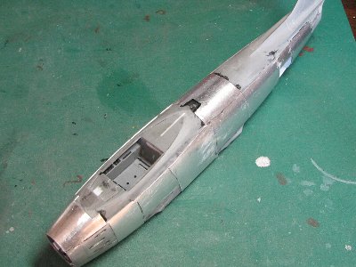
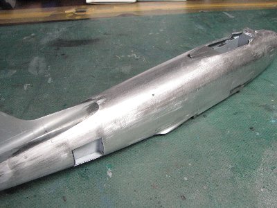
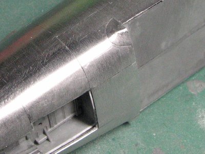
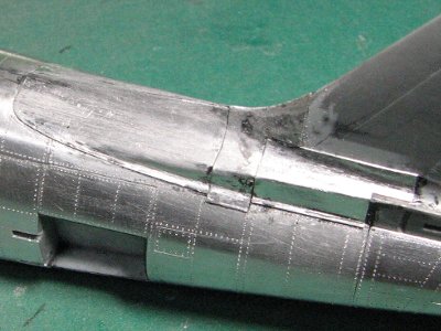
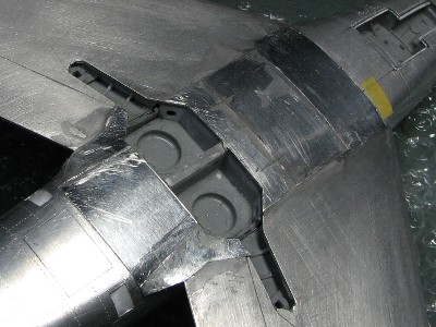
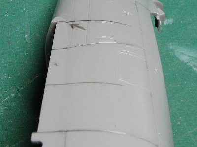 This is before the correction. The kit fuselage bulges out (see pencil lines). And the actual aircraft doesn't have the dent near the wing leading edge (see arrow). |
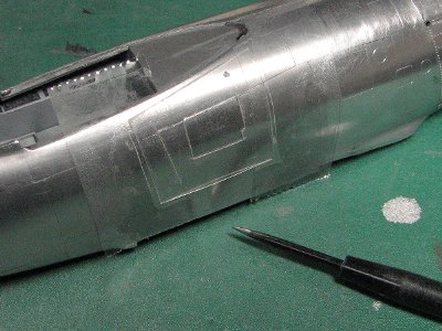
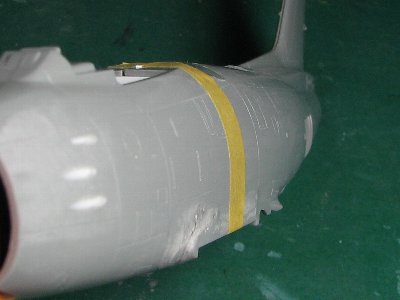 After correction, the fuselage side vertically rises straight from the wing root (see yellow masking tape). The dent near the wing leading edge is filled with CA glue. |
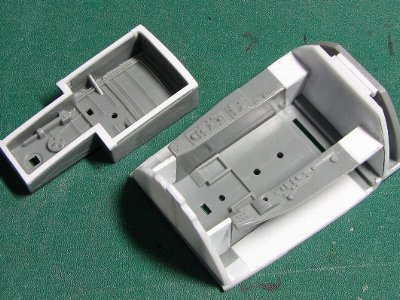
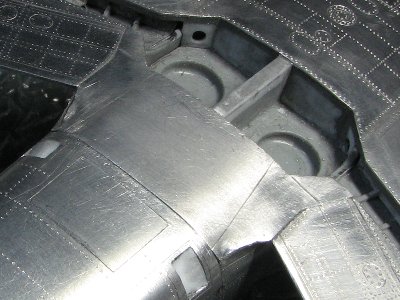
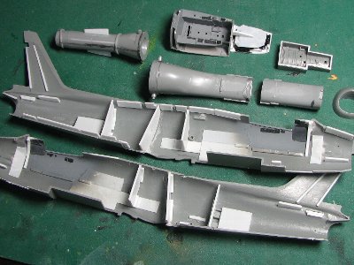 The fuselage is reinforced thoroughly with bulkheads, the cockpit floor and other parts. |
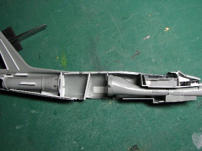 Each part is tightly located like this. The weight ballance (fifteen 4mm steel balls) is glued in front of the cockpit. |
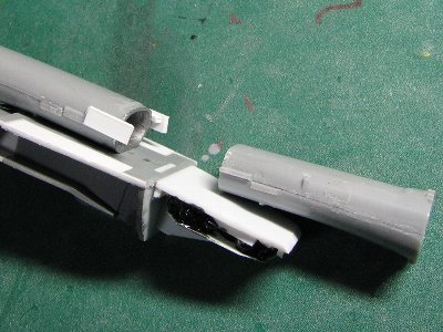 The front half of the intake duct is to be glued on the intake lip. |
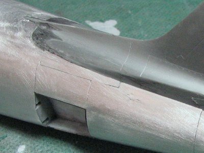
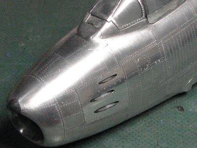
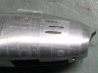
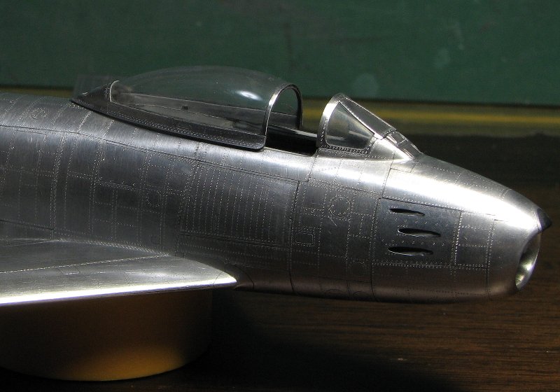
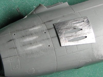 Gun muzzles are drilled out and filed in the aluminum sheet before gluing it on. Notice that the upper hole is smaller than others and three holes are not parallel on the plane panel. The lower panel line of gun muzzle panel is corrected according to the pencil line. |
|
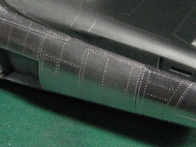
1. 0.3mm aluminum sheet is annealed on the kitchen gas grill. 2. The panel is cut out roughly with scissors. The backside of the panel is sanded with rough (#120 grit) sand paper before gluing it on. 3. The panel is pressed and formed on the mold (I use another kit) with a stick or spatula. 4. At the same time, the panel outline is trimmed with scissors and sand paper. 5. Above process 3. and 4. are repeated to adjust the panel shape until the panel matches the corresponding area on the model surface. 6. Small holes are drilled into the plastic surface to accommodate the excess glue (of cause holes should avoid rivet lines). 7. CA glue or epoxy glue is thinly applied on the plastic surface. (I use Black CA glue for fuselage but I recommend epoxy glue.) 8. The aluminum panel is set and fixed with scotch tape. 9. Urethane foam is put on and bound tightly with scotch tape. 10. After gluing, the surface of aluminum is sanded. Panel lines or rivets are engraved. Finally, the surface is polished with fine (800 grit) sand paper. |
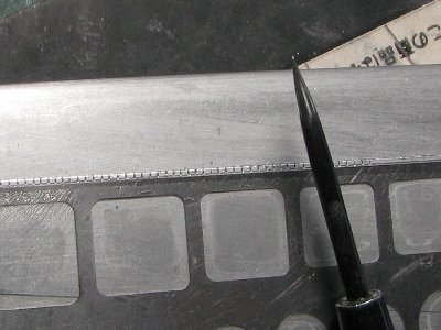
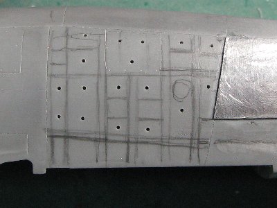 Rivet lines are drawn with pencil and holes are drilled. |
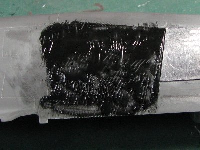 Black CA glue is applied thinly. |
 The panel is fixed and coverd with scotch tape. |
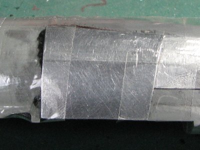
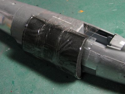 1cm thick urethane foam is put on the aluminum immediately and attached tightly with scotch tape. Then excess glue and cavities are removed. |
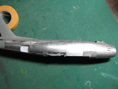 The line of starboard panels is almost finished. |
 The port line of panels is finished, and the upper line follows. |
 The panel line in front of the windshield was omitted on the kit. |
 The surface is roughly sanded with 240 grit sandpaper to achieve even surface. |
 The gap at the tail fin filett is filled with black CA glue. |
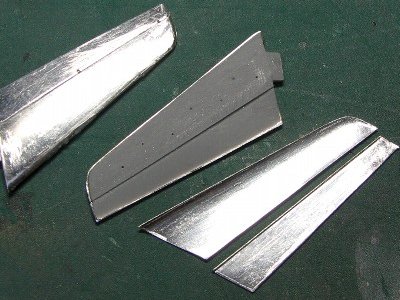
 The intake lip consists of four pieces. |
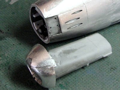 The engine duct is glued to the intake lip to assure smooth transition between the lip and duct. |
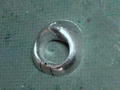
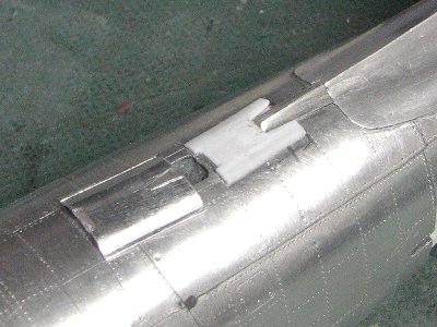
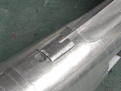
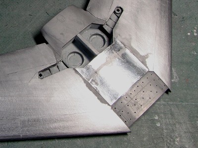
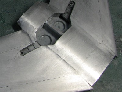
 The 6-3 wing aircraft has small semicircular filet on the fuselage. It is unexpectedly difficult to create this filet panel. |
|
The number of fuselage panels is about 50. It took about thirteen minutes for each panel. So, total working time is almost 25 hours. Well, some modeler can finish whole model in that time.
|
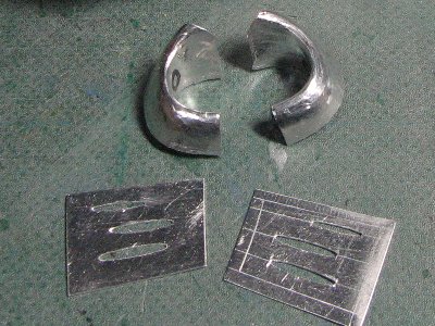
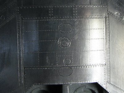
 This template is made of 0.2mm clear plastic sheet and fixed with scotch tape. |
 The "D" shape panel is engraved with two layers of templates. |
|
|
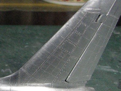
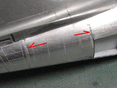 There are some dimples along the panel line near the airbrake. |
 Fortunately, there is no dimple on the port tail. |
|
|
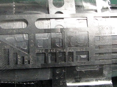
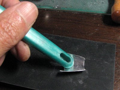
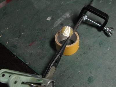
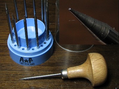 Beading tool. |
 |
|
|
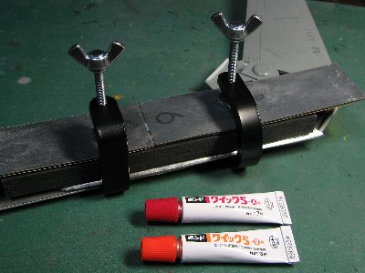
 The tail fin filet panel is glued "on" the top of the fuselage panel, not "side by side". |
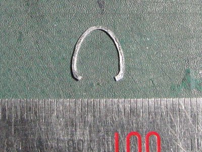
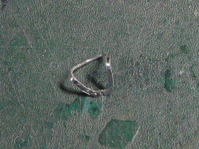
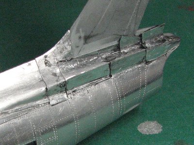 These filet panels are "W" cross section shape. Therefore forming is rather difficult. 0.3mm sheet is too stiff to form, so I used 0.2mm thick alu instead. |
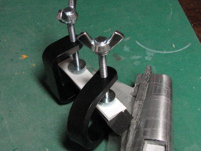 These mini clamps are used for pressing. |
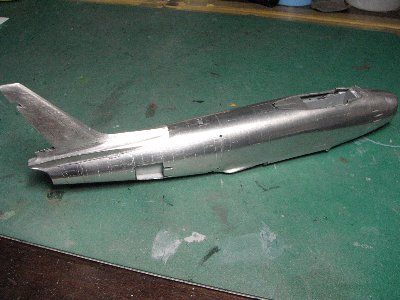 All aluminum panels of the fuselage and tail fin are finished. |
|
|
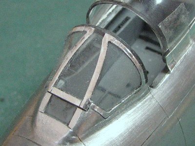
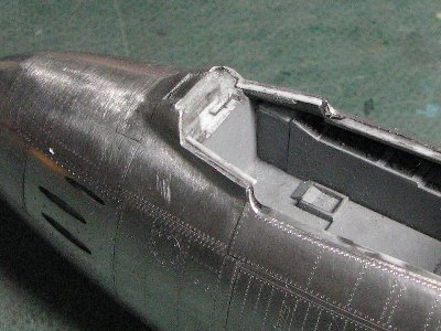
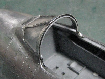
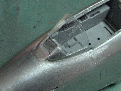 The kit windshield lacks the frame on the front edge. The frame is molded on the fuselage parts instead. |
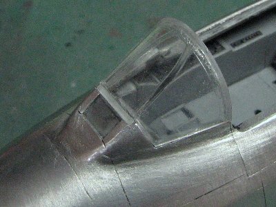 Two-ply 0.4mm clear plastic sheet are glued on the front edge and the fuselage is cut out. |
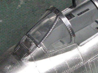
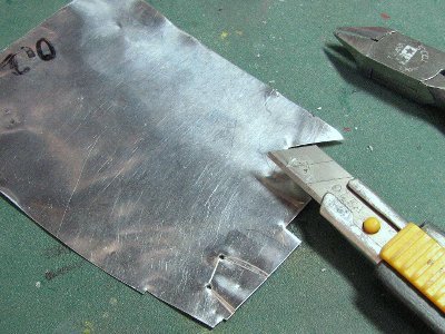 Window frames are made of 0.2mm thick aluminum sheet. This is for the side window of windshield. |
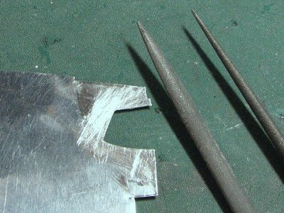 This kind of part should be cut and trimmed on the inside first. |
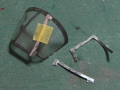 Then the outside is cut and trimmed. The backside portion of the frame is painted black. |
 The separation of the frame parts is same as actual aircraft. |
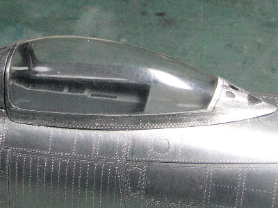
 The rear end of kit canopy is a little different in the cross section. |
 Lower sides are sanded to emphasize the pinched shape (like Greek alphabet Omega). |
|
|
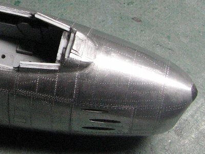
 Before removing aluminum panel from the nose, I prepared the new panels. |
 The nose ridge panel is removed and cavities appeared. If I engraved rivets, dimples would occur. |
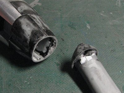 The intake lip part is cut out to shorten the length of the nose. |
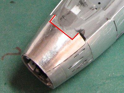
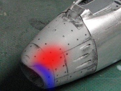 The red portion is sanded to sharpen the nose ridge line. The blue portion is sanded to sharpen intake lip as well. |
 The nose access panel should be formed to trace exact 3D curved surface. The panel is pressed on the rubber mat with a round tool. |
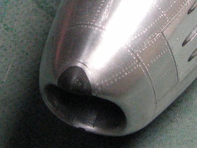
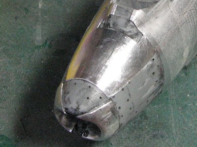 The order of gluing the panels is important. It's as follows ; intake lips (both side) -> upper nose access panel -> upper lip -> muzzle holes -> small panel fwd muzzle -> lower nose. |
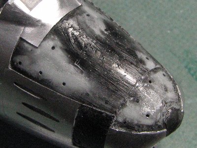
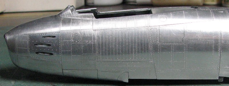
 The surface looks uneven but the roughness is within the thickness (0.3mm) of aluminum material therefore it can be sanded smooth. |
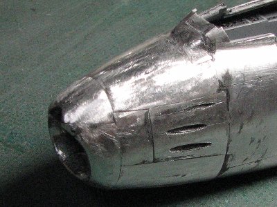
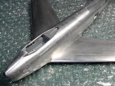
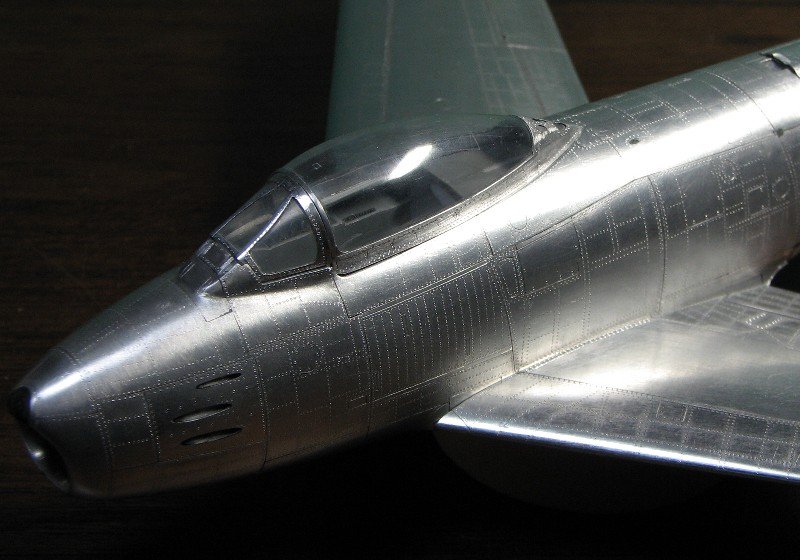
 Sanding and riveting are finished. The gum muzzle panel is polished with fine grit sandpaper and rubbing compound. |
|
|
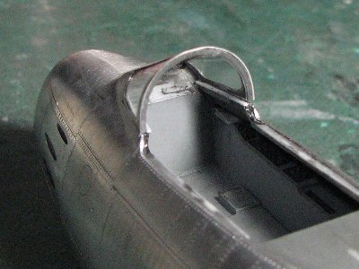
 I revised the side window frames. The frame is fixed with tweezers and clamps. |
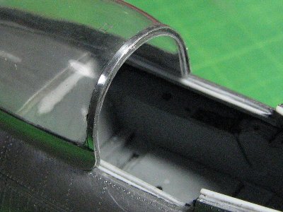
 The windshield guide is glued on. |
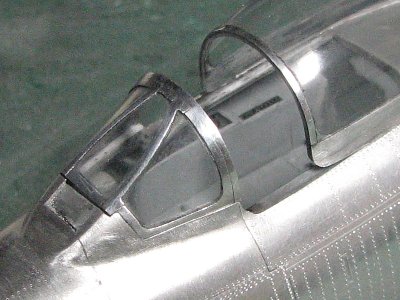 This is the revised frame. The curvature of the backward corner is enlarged. |
 Rivets are engraved and polished. |
 The rear end of the windshield is less detailed. |
 I cut down the plastic portion and glued the stretched sprue. |
 The front edge of the canopy is cut and the strip of 0.2mm plastic sheet is glued on. |
 Rivets are engraved on the canopy frame as well. |
|
|
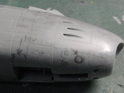
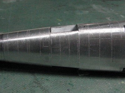
 Panel lines and rivets are engraved. I made a mistake in the panel and rivet lines of the access panel. (I'll explain that later.) |
 The small panel forward of the dorsal fin is made of 0.3mm aluminum sheet. The base made of plastic sheet is inserted to prevent the deformation. |
 Model A, E and Canadair Sabre don't feature this small panel. |
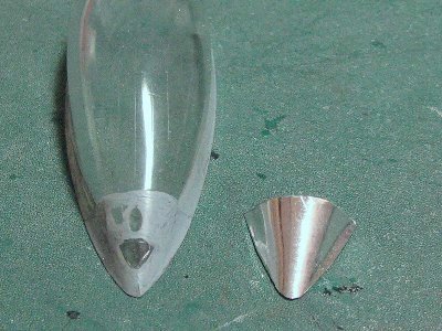
 The shape of the nose radar rim is copied on the masking tape and the aluminum sheet is cut out accordingly. |
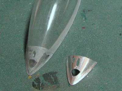
 The rim is bent and glued on the nose. The width of the radar (excluding rim) is 5.7mm in 1:48 scales. |
 Black CA Glue was applied and sanded. The small opening on the lower lip is the gun camera. |
|
|
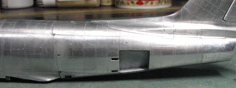
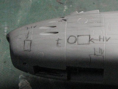 No small rectangular panel aft the intake, adding circular panel for E model, no rectangular panel next to this panel, no rectangular panel on the lower fuselage. Three handgrips on the gun access panel (no photo). |
 Adding the small rectangular outlet in the rectangular panel for E (and early F?) , in this case, no small elliptical outlet. Adding the vertical panel line above the airbrake (both sides). |
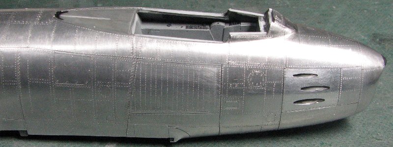
 Adding the small circular panel under gun muzzles, no rectangular panel (same as the port side). |
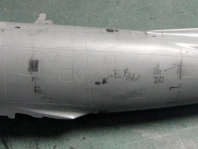
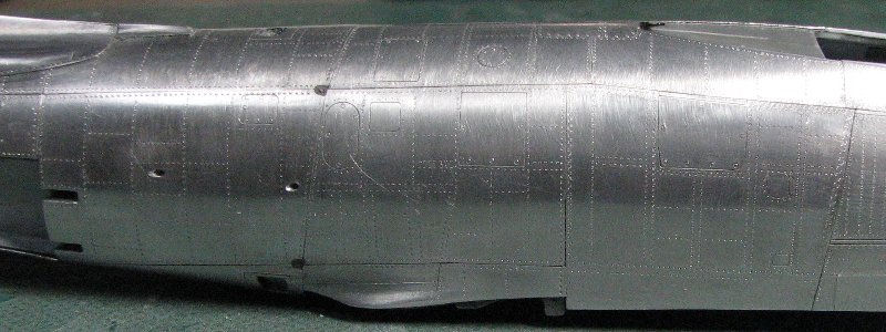
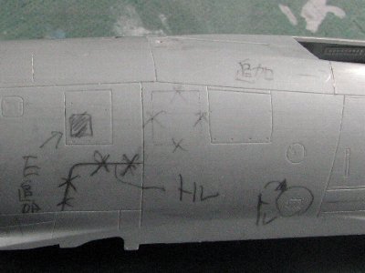 No small rectangular panel on the wing root, no "XXXX" panel line, small outlet is the same as port, adding the vertical panel line aft the cockpit (both sides). |
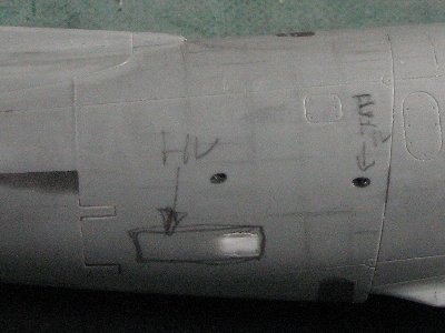 No bulged air intake, small elliptical outlet is the same as on the port side. |
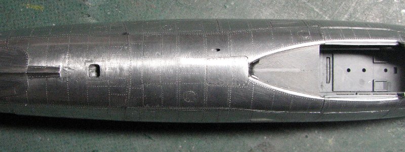
 No "XXXX" panel lines (common with all A to F model), A and E model has the large trapezoid panel on both side and no small panel above this panel (F has this small panel and no trapezoid panel), the small rectangular panel is port only (A and E). |
|
Please see this photo for lower fuselage small outlets of model A to F-30.
|
 |
 |
 |
 |
 |
 |
 |
 |
 |
|
|
| [Original wing] (model A to midstream of F-25 and 30) | |
| chord | root 10.3ft tip 5.3ft |
| span | 37.12ft |
| angle of attack | root +1deg. tip -1deg. |
| sweep angle | 35deg.(25%chord) |
| dihedral | 3deg. |
| airfoil | root NACA 0009.5-64, tip NACA 0008.5-64 |
| chord thickness ratio | root 9.5%, tip 8.5% |
| [6-3wing] | |
| chord | root 10.85ft, tip 5.53ft |
| sweep angle | 35deg.41min.(25%chord) |
| chord thickness ratio | root 9%, tip 8% |
| [Horizontal tail fin] | |
| Span | 12.75ft |
| sweep angle | 35deg.(25%chord) |
| dihedral | 10deg. |
|
The kit airfoil is slightly different. The leading edge is a little bluntl. The front half of the actual airfoil is like on P-51 Mustang's wing. And the maximum thickness is 40% of the chord. But I noticed this after aluminum work was done so the model is not corrected except for the leading edge.
|
 The kit wheel wells are shallow a bit. So the ceiling is cut out and the new sidewalls are made of 1.2mm plastic sheet. |
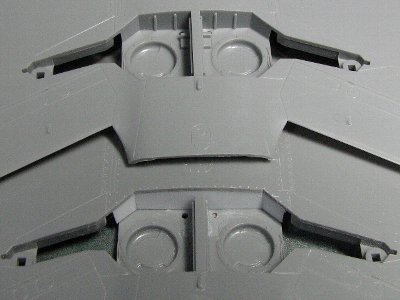 The upper is the original kit and the lower is the correction. The depth is increased by 2mm. |
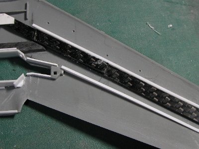
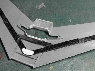 The wing is reinforced with carbon fiber material. |
 Wing spars of plastic sheet (white) are installed to maintain the wing thickness. |
|
|
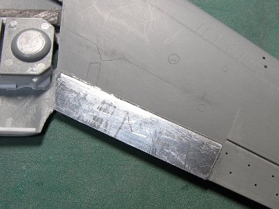 Aluminum sheet is glued from the upper surface. |
 The leading edge of the aileron is bent to "L" shape. Glue excess gates are very effective. |
 Epoxy glue is used for the wing. Mini clamps and urethane foam are used for binding. |
 All panels of the starboard upper wing are glued. |
 The starboard surface is sanded with 180 to 400 grit sand paper. |
 The lower panel is simply glued on the under side of upper panel at the trailing edge . So the edge of the upper panel is sanded thoroughly before gluing. |
|
The leading edge and wing tip are divided into upper and lower panels on my model. The actual aircraft features the single, seamless panel, but it is very difficult to recreate this and resulting seam is not really noticeable when the surface is polished.
|
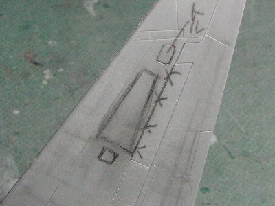
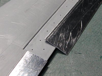
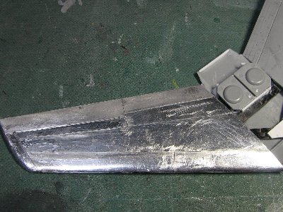
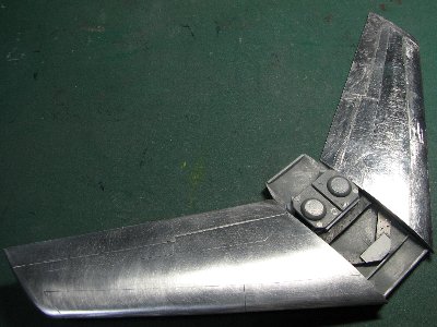
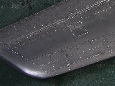
 The horizontal tail fin panels are simply divided into upper and lower ones. |
 Rivet lines are copied according to the station numbers based on the references. |
|
|
 The final aluminum panels are going to be glued. |
 The wing part is not glued to the fuselage part yet. Both surfaces are sanded smooth. |
 The surface is sanded with 320 to 600 grit sand paper. |
 |
|
|
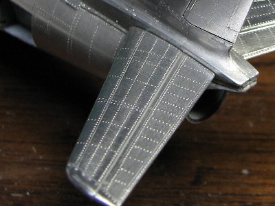
 The ladder pattern is engraved like this. |
 After engraving panel lines, the surface is sanded with 600 grit sand paper. Then rivers are engraved. |
|
|
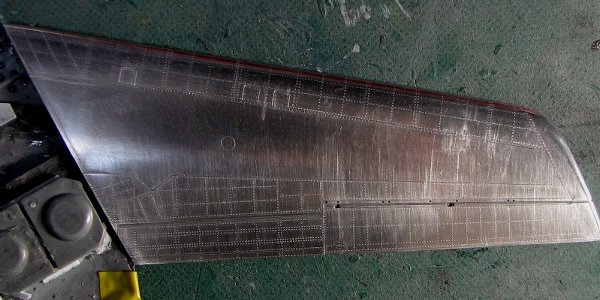 The starboard upper wing is finished except for the center section. After riveting, the surface is sanded with wet 600 grit sand paper followed by dry 800 grit. |
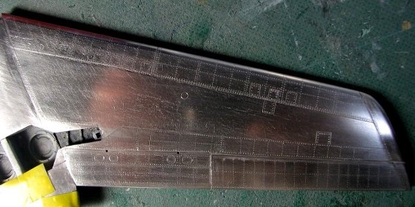 This is the lower wing. The rivet lines between the rear spar and flap/aileron are not quite accurate. Please refer to the same portion of the upper wing. |
|
 Some panel lines between the wing and fuselage are inaccurate. Please consult the references. Wing connecting bolts are riveted with #6 beading tool. |
 The wing is dry-fit to the fuselage and sanded carefully. |
|
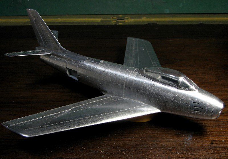
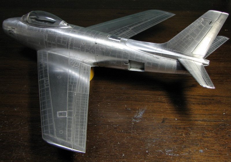
Finally the kit is taking its shape. The wing and horizontal stabilizers are not glued on yet. |
 |
 |
 |
 |
|
|