Shoki II-otsu (Hasegawa 1/48)
6/Feb/2009
|
|
Great thanks to Mr. Mario for checking my English text!!
|
|
|
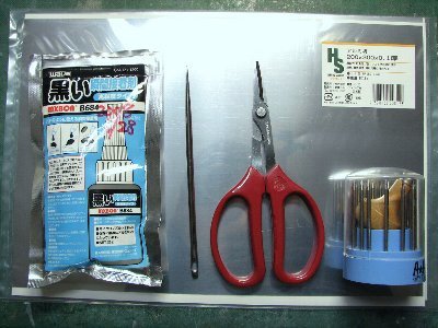
These are tools and material. From the left to right, Wave's Black super glue, metal needle serving as a spatula to form the sheets, scissors and beading tools for riveting. |
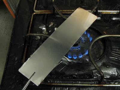 The 0.2mm aluminum sheet was annealed over the kitchen gas burner. |
|
I heated the aluminum sheet for 1 - 2 minutes about 5cm above the very low flame until it softened. Then I let it cool off naturally. Next, I cut the sheet to the rough shape with scissors, sanded the rear side with rough sanding paper, pressed on the model surface with the large needle serving as a spatula (but you can use any similar tool for this task). I used scotch tape to temporarily fix the sheet on the model. Then I trimmed it to the accurate shape with scissors, hobby knife and sanding paper. I used the black superglue made by Wave (check their websiteÅc). This glue needs about 5 minutes to set, so you can adjust the position of the panel. My modeling friend uses rubber adhesive diluted with thinner and applies it with a brush. Another friend uses a regular super glue. The aluminum sheet could be trimmed after gluing with hobby knife or hobby chisel. After several panels were glued, the surface was sanded with metal file and rough sanding paper attached to the stick. Then rivets and panel lines were engraved. Aluminum was so soft that engraving could be done like as plastic. Finally, the surface was sanded with 600 grit sanding paper. This finish is suitable for WWII aircraft. For the post-war jets I would use 1500 grit. Of cause you use polishing compound afterwards if a mirror finish is required (I'm going to try it one day). |
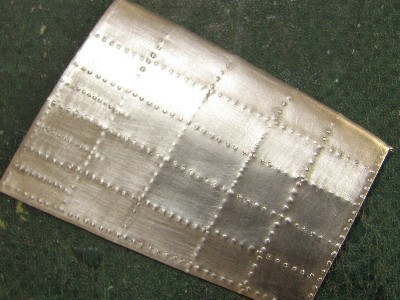
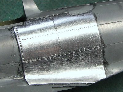 This is the test piece. Rivets are #1 (0.3mm) beading tool. |
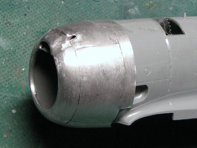
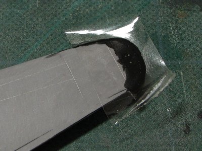
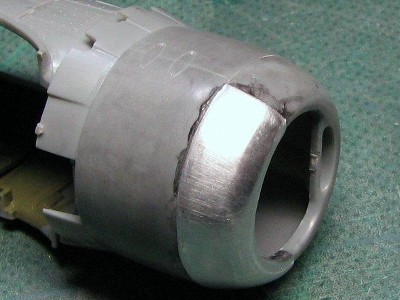 The aluminum sheet can be formed into complex curves such as this cowl lip. |
|
The aluminum sheets of various thicknesses (0.3mm, 0.2mm, 0.1mm, 0.05mm) can be found at various metal and craft shops in your area. The 0.1mm sheet is easy to form however 0.2mm could be easily sanded as needed. Some modelers use a self-adhesive aluminum foil. But, it doesn't stick well on the complex curves, the surface is too soft and can be damaged easily even after you are finished. Therefore aluminum sheet remains my choice.
|
 This is the test piece of convex rivets on the 0.2mm sheet. |
 I used #2 or #3 beading tool. It may be a little over sized for 1/48 scale, what do you think? |
|
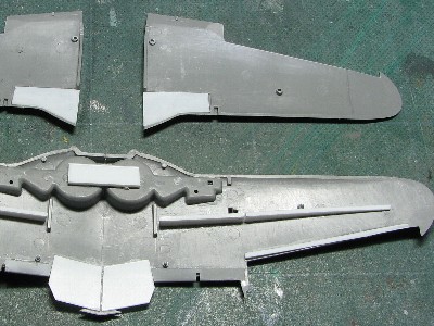
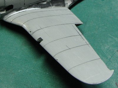
Level 1 The outline of the ailerons on the top of the wings is wrong. The cord is the same as on the lower wing i.e. it needs to be rescribed on the top wing with a shorter cord. The fuselage ammo box hatch is too small for type II-otsu or II-hei. This correct for type I and II-kou only. The leading edge of the tail fin is too thick and should be sanded down.Level 2 The side shape of the sliding canopy, propeller blade (narrow), fuselage cross section near wing filet, cross section near tail fin and airfoil (especially blunt leading edges) need corrections. |
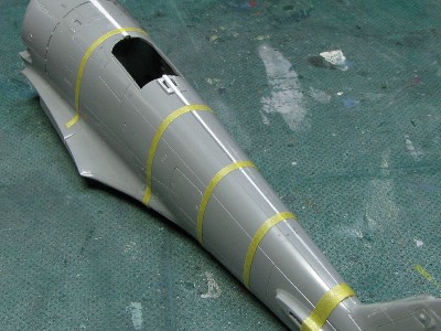
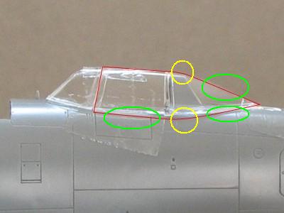 The red line is correct. The green portions are straight line and the curves of yellow portion are more clear. |
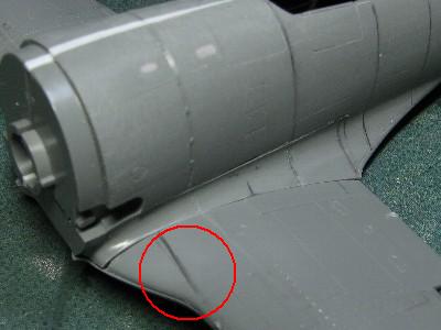
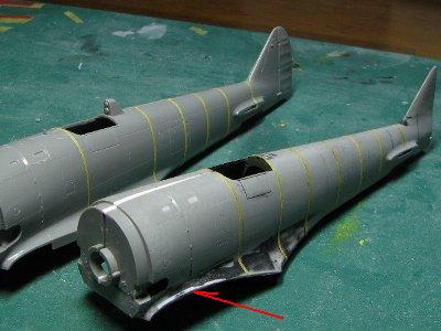
 The depression near the red circle is not so pronounced on the actual aircraft. |
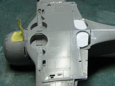
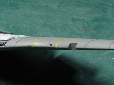
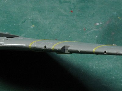
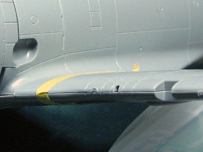 The leading edge is too blunt. Please see the yellow tape or landing light. |
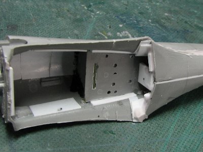
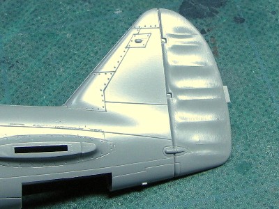 The connection of the tail fin to the rear fuselage isn't good. |
|
Level 3 Hasegawa's fuselage is too narrow, too much shaped-up right after engine cowling. The width of the fuselage is about 2mm smaller in the canopy area. As far as the rear fuselage cross section shape is concerned, the curve of fuselage side is insufficiently bulged and the top and bottom should be more sharply rounded. The actual a/c fuselage cross section shape is more like "rounded diamond" as opposed to kit's "rounded rectangle".The kit's wing is too thin and the airfoil is off. The upper curvature is too pronounced and the lower one is not sufficient. The leading edges are blunt and the whole wing is mounted lower by 1mm.
|
| Engine | Diameter | A/C |
| Ha-112(Kinsei) | 1,218mm | Goshikisen(Army type 5 fighter), Suisei |
| TwinWasp R-1830 | 1,224mm | F4FÅAP-36 |
| Ha-41 (Ha-109) | 1,263mm | Shoki |
| BMW 801 | 1,316mm | FW190 |
| Ha-101 (Kasei) | 1,340mm | Raiden, Tenzan |
| Double Wasp R-2800 | 1,341mm | F6FÅAF4UÅAP-47 |
| Wright Cyclone R-2600 | 1,397mm | Helldiver, Avenger |
|
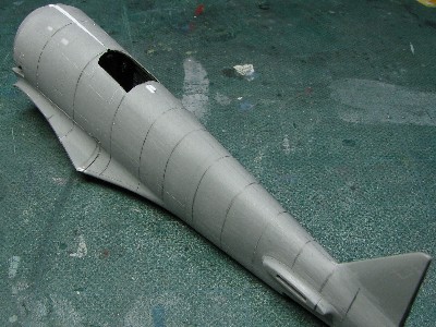
Ha-109 engine didn't have a large diameter in comparison to the US or European engines. The large nose diameter was the result of the gap between the engine and cowling. Some drawings depict the fuselage with steeply curved lines towards the tail. However the actual A/C had almost straight lines, bent only a little bit bent from cowling end to the tail fin. I calculated the wing thickness from photos. Then the cord-thickness ratio was 17% at the root (excluding landing gear bulge of leading edge) which cannot be considered thin. So the common view should be rewritten that "The diameter of cowling excessed the engine and the fuselage sideline was almost straight from the cowling end to tail and the wing was small but not thin".
|
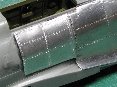
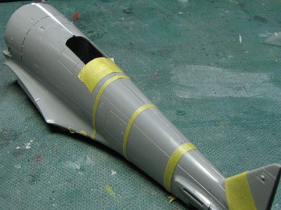
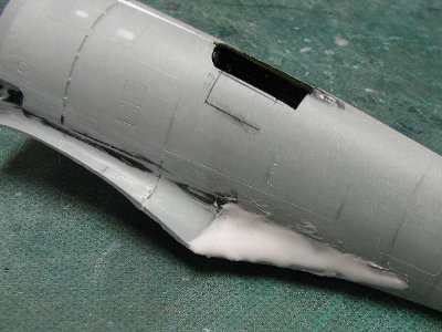
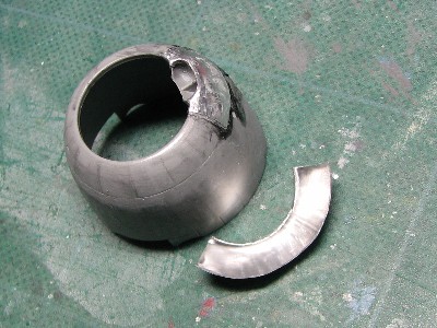 The 0.2mm aluminum sheet was used. I started from the front top panel and the next was the front side panel. |
 After all of the front panels were glued, I trimmed panels at the panel line. The 0.3mm plastic sheet was glued on the cowl side to correct the fuselage line. |
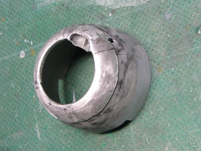
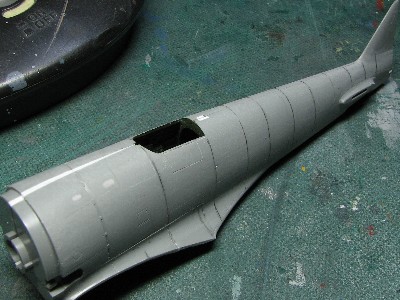
 The surface was sanded with 400-grit sanding paper. |
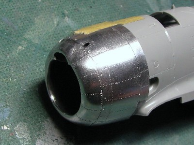 Then rivets (#0 and #4 beading tools) were engraved. The surface was polished again. |
|
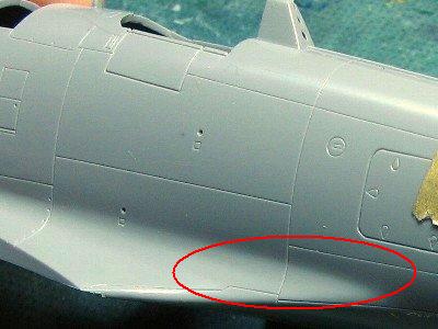
Glue is especially important. I used scotch adhesive tape to fix the panel. And I think a large panel is difficult to glue, so you better divide the surface into small panels and glue them one by one. |
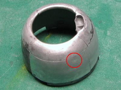 There is a bubble behind the red circle. This dimple cannot be fixed, so I had to remove the panel and repeat the procedure. |
|
|
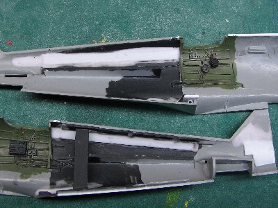
 I inserted shims of white plastic at the centerline of the fuselage. But it was not good method, for the cross section shape became no good. The upper portion of fuselage became too wide. So this method was rejected. |
|
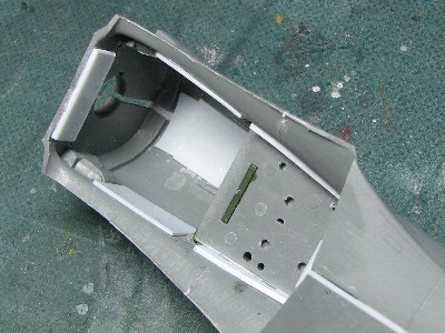
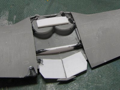
The cross section shape of rear fuselage was like round diamond. So I removed shims and bent the fuselage parts at the half point of height, and to prevent them to loose this shape I glued the support plate on the inside. |
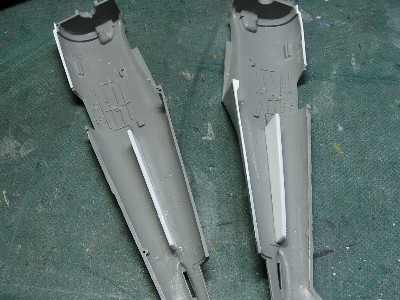 The fuselage was bent to correct cross section and support plates (white plastic) were glued. Shims at the front and lower of fuselage remained in place. |
 The upper portion became narrow and the side extended. Then the image of cross section became good. |
 Contact surfaces were reinforced with pieces of plastic. The plug was inserted in the fuselage. |
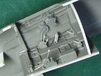
 The cockpit floor and bulkhead were widened with white plastic sheets. These parts worked for reinforcement, so the width should be adjusted carefully. |
|
The cockpit of Type 97 fighter was painted dark blue gray. In 1940, the color of the cockpit changed to Aotake (clear blue) and it was applied to early type of Hayabusa (Oscer) and Shoki. (Hayate /Frank was unknown, if exist, I think there were experimental type only.) In June 1943, Aotake of cockpit was discontinued and changed to gray green and it was applied to Hayabusa, Shoki and Hayate. But there was probability of some delay at production lines. This gray green color was similar or equal to the cockpit of Nakajima made Zero fighter or Saiun or to the propeller of Hayate. In the middle of 1944, when "No.7 yellow green" (dark brown or dark drab : the name was "yellow green" but the actual color was not green) was introduced to camouflage, cockpits were also painted No.7 yellow green. Considering the above facts in relation to Shoki, early types were Aotake, and in the middle of 1943, it was changed to gray green in production of model II-Kou or II-Otsu. Model II were produced from November 1942 until the end of 1944, and guessing from the number of production of each model, production of Otsu model started in summer of 1943. Late model of II-Hei might be No.7 yellow green.
|
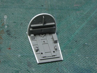
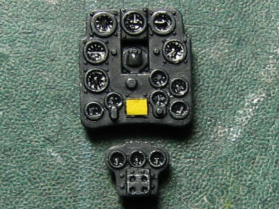 Kit's instrument panel was good comparing with photos of actual A/C. |
 Additional parts were mainly from Tamiya Zero fighter. For I bought two boxes, so one set of cockpit remained. |
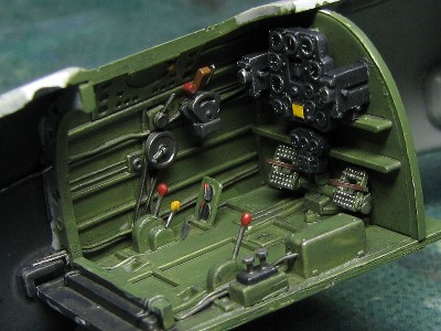 Gray green was the last Zero's cockpit with a little green added. Red and yellow knobs were perfectly fiction. |
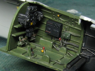 The electrical distribution panel is from the kit. |
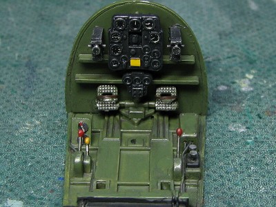 The detail was different but no corrections were made. |
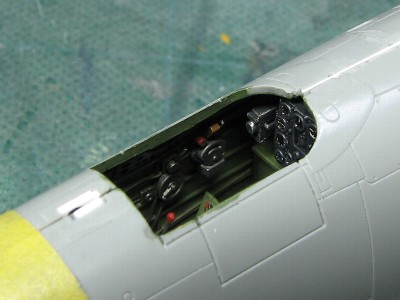 After the fuselage halves are glued together most of the cockpit cannot be seen anyway. |
|
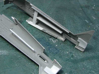
The position of kit's wing was a little low, and the thickness of wing would be increase, difference in level existed between the wing and fillet. So I cut out the portion of the fillet, cut out 1mm of cutting line and glued again. |
 Super glue putty and plastic plate were filled in the inside. |
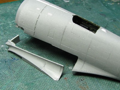 The fillet was cut out to raise the position by 1mm. |
 The "shoulder" of the fuselage was shaved to round triangular shape. |
 The front half of the fuselage was almost unchanged. |
 The fillet was reinforced with plastic plates. |
 The fillet was cut more than 1mm at the boundary of the wing. |
|
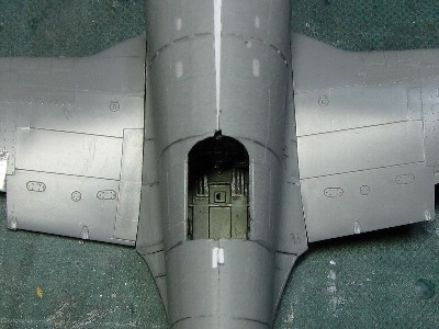
The wing washout was minus 2 degrees. The angle of incidence was 2 degrees at the root, 2 degrees at the boundary of inner and outer wing and 0 degree at the tip from a certain reference. This kind of washout (outer wing only) was similar to Zero fighter. The aluminum sheet was not put on the aileron, so the aileron was cut out. The trailing edge of the flap extended beyond the wing trailing edge. This design was difficult for aluminum work. So the flap was also cut out. |
 Some reinforcements were added. |
 The guide for flap was glued. |
|
|
 I think this panel line (marked with pencil) seen in some drawings and new 1/32 kit didn't actually exist. |
|
|
 The fillet was reinforced again. |
 Super glue putty was applied on the fuselage. |
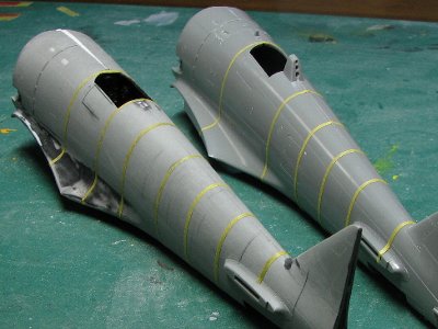 The left is corrected model and the right is the original kit. |
 To level the wing top and fillet, plastic plate was glued (the arrow) and filled with black super glue. |
|
1. The upper and lower curvatures are almost same (symmetrical). 2. The airfoil is similar to the lens' shape, curvature of the front half is insufficient and the rear half exaggerated. 3. The curvature of the leading edge was too large (blunt). The decrease in the rate of thickness ratios of the inner wing and outer wing were different. In another words, the outlines of upper and lower wing were slightly bent at the middle from the front view. |
 An additional reinforcement beam was glued to maintain the dihedral. |
 The black super glue was applied to the edge. |
 The leading edge was sanded to a sharper shape. The white plastic plate of the back was visible. |
 This was the original kit. |
 This is the corrected airfoil. |
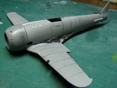 The fuselage was glued to the wing. |
|
|