Shoki II-otsu 2
6/Feb/2009
|
|
|
|
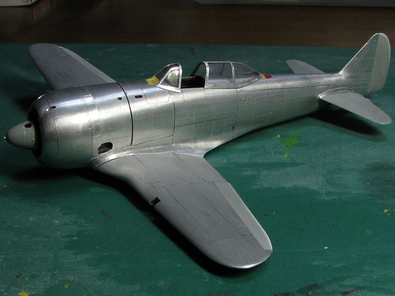
 All rivet lines were determined from the photos of the actual A/C not from drawings. |
 Kit's panel lines were a little different. Pencil lines are correct. |
|
|
 I tested these glues. |
|
|
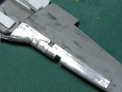
 First of all, the panel near horizontal fin was glued. Next, the right side panel was attached followed by the lower narrow panel. |
 The panels were held in position with scotch tape until the glue hardened. |
 The annealed aluminum sheet can be formed very well even on the tight curves such as the wing root fillet. |
 It was glued on the fuselage. |
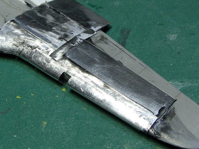
 The leading edge of tail fin was formed like this. |
 Excess glue presented no problem as it was sanded down after it set. |
 The surface was sanded with 320 grit sanding paper. |
 The surface was finished with 600 grit sanding paper. |
|
|
 The aluminum work is suitable for mobile modeling. Tools and materials could be stored in this small box and carried easily. |
|
|
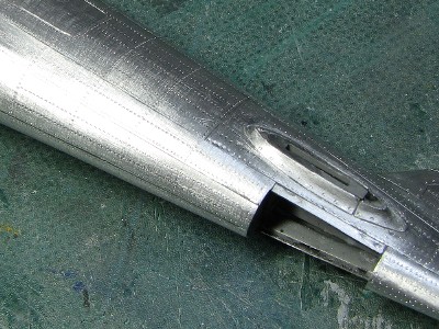
 The upper outline of supercharger air intake was corrected. The plastic sheet was glued and sanded. |
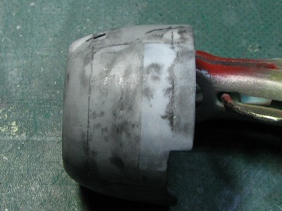 The outline is bent at the point of the panel line. |
|
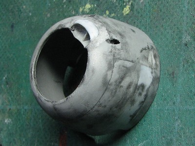
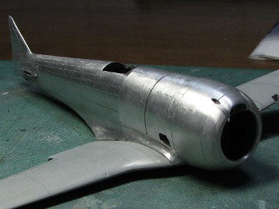
The diameter of the cowling leading edge became shorter by about 0.5mm caused by the thickness of aluminum sheet. The leading edge should be enlarged before gluing the aluminum sheet. |
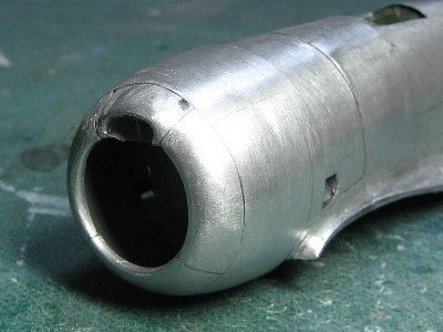 The air intake was enlarged to upwards. Then the shape was improved. Some of the kit's panel lines were corrected. |
 I drilled out the gun openings, engraved cowl flaps and made the cut-out for the exhaust. |
|
|
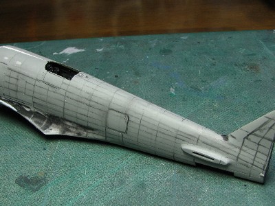
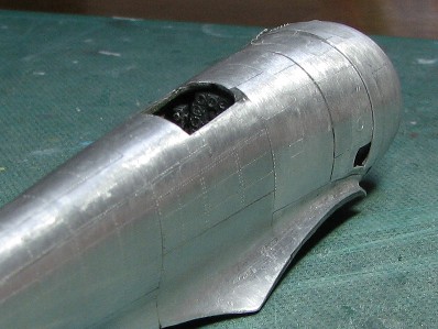
 The starboard fuselage was done. After the surface was sanded, wash was applied using Tamiya Weathering Master. |
 Next was port fuselage. The large dimple appeared. |
 The panel was removed and the base was cleaned. |
 The new panel was 0.3mm aluminum sheet to reduce the influence to blend into the surrounding surface. The sheet was cut and pressed carefully. |
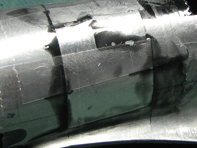 The panel was glued and fixed with scotch tape. |
 The surface was leveled off with the metal file and rough sanding paper attached to a stick. This repair work took almost one hour. I was so tired. |
|
|
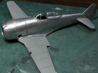
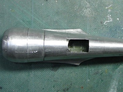 The width near the cockpit was increased by 2mm and the fuselage outline became more accurate. |
 The transition from the cowling and fuselage was like this. |
 Please compare with the actual aircraft. |
 The wing was combined. The colors of the front half and rear half were different due to different polishing. The front half was sanded with lower-grit sandpaper. |
|
|
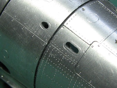
 Rivets and fasteners of cowling were finished. |
 Fasteners of access panels were made with #3 (0.4mm) beading tool. |
|
|
 Ha-109 engine was came from the kit. |
 Plug cables were made from 0.3mm soldering wire. |
|
At first, I used the 0.1mm aluminum sheet, but it was too soft and hard to treat. So I decided to use the 0.2mm sheet. |
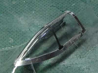
 The 0.3mm plastic sheet was glued on the lower edge. |
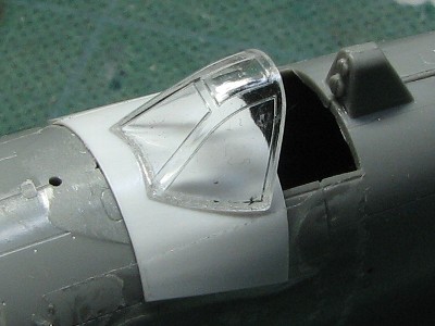
 The 0.3mm plastic sheet was glued on the canopy too. |
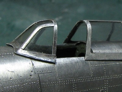
 The rear half of the upper line was sanded to be straight. The lower line was also corrected. |
 I checked the outline. Mmmm, OK! |
 Canopy frames consisted of 6 parts. First, the front frame was glued. |
 The portion of frames was painted black. And frames were glued with Black super glue. |
 The shape of the frame was traced with tape and knife. |
 The lower edge was to be adjusted afterwards. |
 The round corner was cut out like this. |
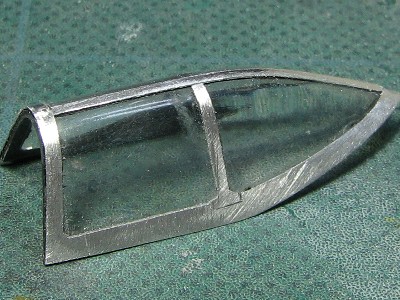 After all the frames were glued they were sanded while the transparent areas were masked with tape. |
|
|
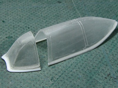
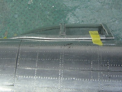 The correction of the canopy and fuselage outline resulted in this gap since the work wasn't completely accurate. |
 The exact shape of the canopy should be narrower at the point of the arrow. But it needed heat pressing of the canopy. Would you accept that challenge? |
|
|
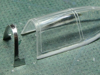
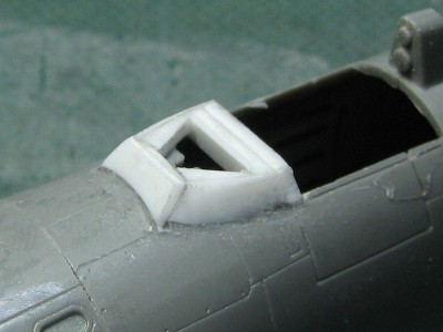 To form the lower frame, this mold was made from styrene sheet. |
 The cross section of the front frame was adjusted with pliers. |
 The outline was checked. It was a little tall due to the thickness of the plastic sheet. |
 Frames were sanded. I took care of the edge on the front frames. |
 The plastic sheet of lower edge was sanded and removed. |
 Looks good! |
|
|
 The horizontal and vertical stabilizers leading edges were sanded sharp. |
 The panel was formed on another kit. |
 The surface of the fillet was sanded. |
 |
|
|
 The oval lines were engraved and the gun exhausts were opened. |
 Finally, the surface was polished with 600-grit sand-paper. |
|
|
 Aluminum sheets were glued from the leading edge. |
 Panels were glued one by one. |
 The upper surface was sanded with a metal file followed by 320-grit sand-paper attached to a stick. |
 |
 I repeated the same on the lower sides. The front of the gear bay was difficult. |
 On the wing tips I simply glued upper and lower pieces of aluminum sheet together. |
|
|
|
|
|
|