Shoki II-otsu 3
6/Feb/2009
|
|
|
The master who built 1/20 F-86F solid model used 0.3mm non-annealed aluminum. He made female molds from resin and pressed the sheet firmly (with the vise?) the sheet with thick rubber plate. He used normal super glue. He didn't sand and level the surface off after glueing since this firm pressure produced sufficiently accurate shape. The nose intake was cast in white metal to a silicon mold. The gun port panel was nickel silver sheet and gun tubes were soldered for the aluminum sheet couldn't be soldered. He used metal primer for railroad model. Sorry I didn't ask for more details. Another master used 0.1mm aluminum sheet. He used rubber adhesive. He diluted it with thinner and spread with brush on both the sheet and model. After the surface of glue dried, he put sheet on the model. After gluing, rivets were engraved. The 0.1mm sheet was thin but the surface was almost flat and no dimples appeared. The other master used 0.3mm annealed aluminum sheet. He engraved rivets on the glass plate before pressing or gluing. After the riveting, the surface was leveled off with stiff column on the glass plate and glued them on because the surfaces of his model featured conicoid shapes almost exclusively. Thus, there is no almighty method. The A method is the best for X modeler but Y modeler prefers the B method. My method is only one of many methods. Try several approaches and choose one that suits you best.
|
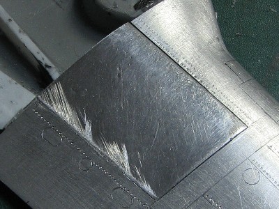
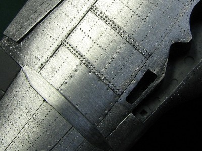
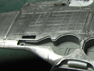
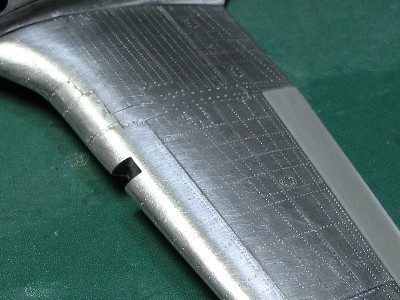 The left upper surface was finished. I could not avoide dimples, orz. But I did not correct them. |
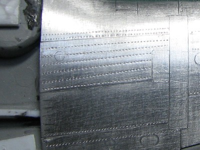 The rivet lines were not parallel. |
 I had to correct them. The panel was removed. |
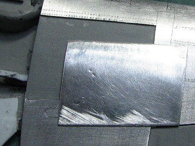
 The new panel was installed. |
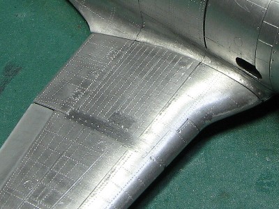 I engraved rivets again. I could manage to keep them parallel. I made a mistake at the rivet line of upper portion of the flap. So please don't copy them. |
 The wing and fuselage were glued together. |
|
|
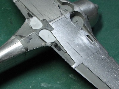
 After gluing the wing to fuselage, the last aluminum was glued. |
 The aluminum was glued on the flap. |
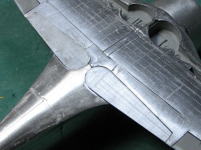 Sorry, I didn't know the exact rivet pattern in this area. |
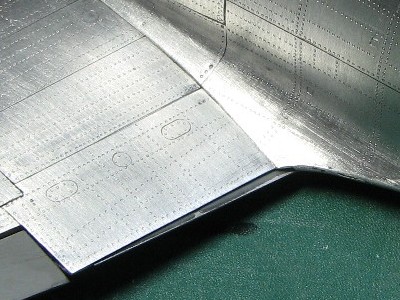 Each trailing edge of the upper wing and flap were sanded to sharp edge. |
|
|
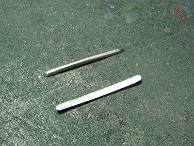
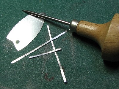 These were tools to make convex rivets. |
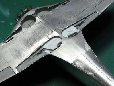
 I was very satisfied with the result however I'm not sure about the pattern accuracy, sorry. |
|
Q: Did you sand down the model surfaces to compensate for the thickness of aluminum sheet?
|
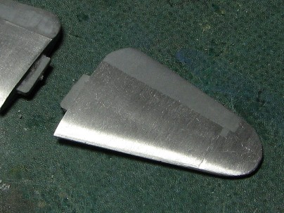 The plastic sheet was glued on the elevator and the surface was sanded. |
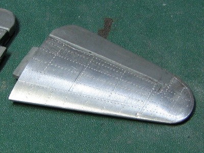 Rivets and the hinge line were engraved. |
|
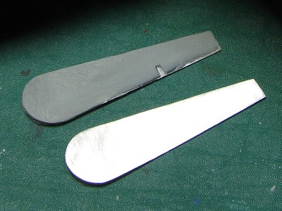
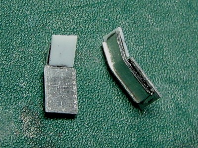
The color of the gear cover inside was as follows. The rib type was natural metal including small upper gear leg cover. Flat type cover insides were typically painted Aotake, it's not confirmed if this happened all the time. The gear legs and wheel discs were natural metal. The wheel wells and the inside of the crescent-shaped wheel cover were painted Aotake throughout all sub-types. The non-annealed 0.3mm aluminum sheet was used. The sheet was cut, pressed to level, sanded with the 600-grit sandpaper and rivets were engraved. Ribs were cut from the 0.5mm plastic plate. The contact surface of the upper fringe rib was very small, so 0.3mm plastic plate was used as a guide. The 0.3mm plastic plate also worked for the connection between the gear leg and cover. Of course the gear leg had to be sanded down to compensate for the thickness of the plastic plate. |
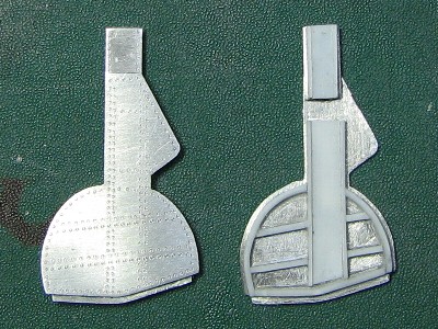 The ribs on the inside were the feature of model II-otsu and II-hei. |
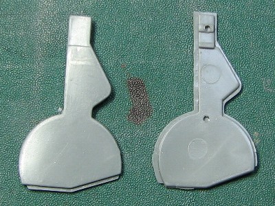 This is the original kit part. This flat type was suitable for II-kow or I. |
 There was some doubt about rivet lines pattern on the cover. |
 The gear leg was sanded down to compensate for the thickness of the cover. This kind of adjustments were necessary for the scale appearance of the model. |
|
|
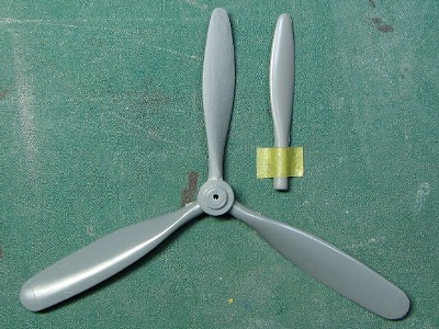 The blades modified using Tamiya Mosquito parts. Original kit blade is on the right. |
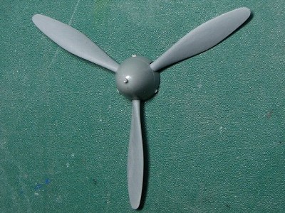 The shape of the kit's spinner is perfect. But new 1/32 kit is not good. |
|
|
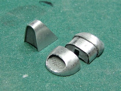
 Oil cooler parts were too small to be formed into the aluminum sheet directly so they were glued on the base (another fuselage in this case) and then the sheet was pressed. |
The aluminum sheet well represents the thin fringe of the headrest. |
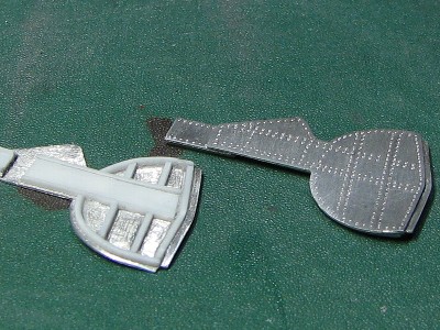
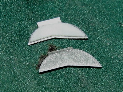 The wheel cover was from the 0.3mm non-annealed aluminum sheet. The inside was the 0.3mm plastic sheet. |
 The small upper gear cover was also from the 0.3mm non-annealed aluminum sheet. The 0.2mm aluminum sheet was bent and glued on the inside. |
|
|
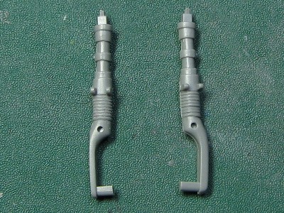
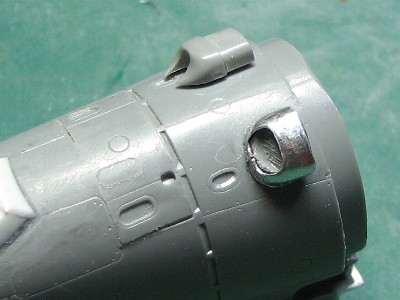
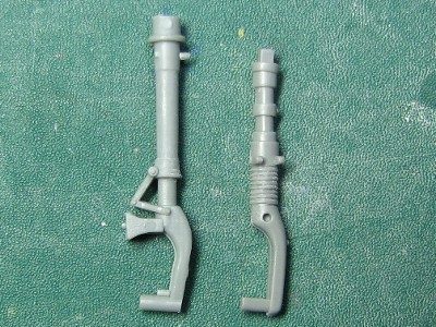 The kit parts are on the right. The upper portion was under-scaled. Hasegawa Zero parts are on the left. The cut was made above the oleo strut. |
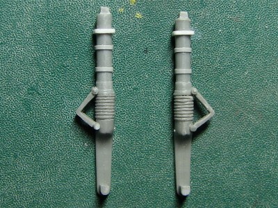 This is the modified landing gear. The torque links come from the kit but were thinned down. The rubber (or leather) covers of the oleo struts were engraved with the etching saw. |
|
|
 The wing attachment bolts cover and aileron actuator covers were shaped from the 2mm aluminum rod. |
 The fringe from the thin plastic sheet was added to the side walls in the wheel wells. |
|
|