Curtiss P-36 P-40 series drawings

H81-A2 Modeling Note


Introduction

A long-awaited new tool 1/48 P-40B kit was released from Airfix. I'd built it as AVG Flying Tigers Hawk H81-A2 flown by Charles Older.

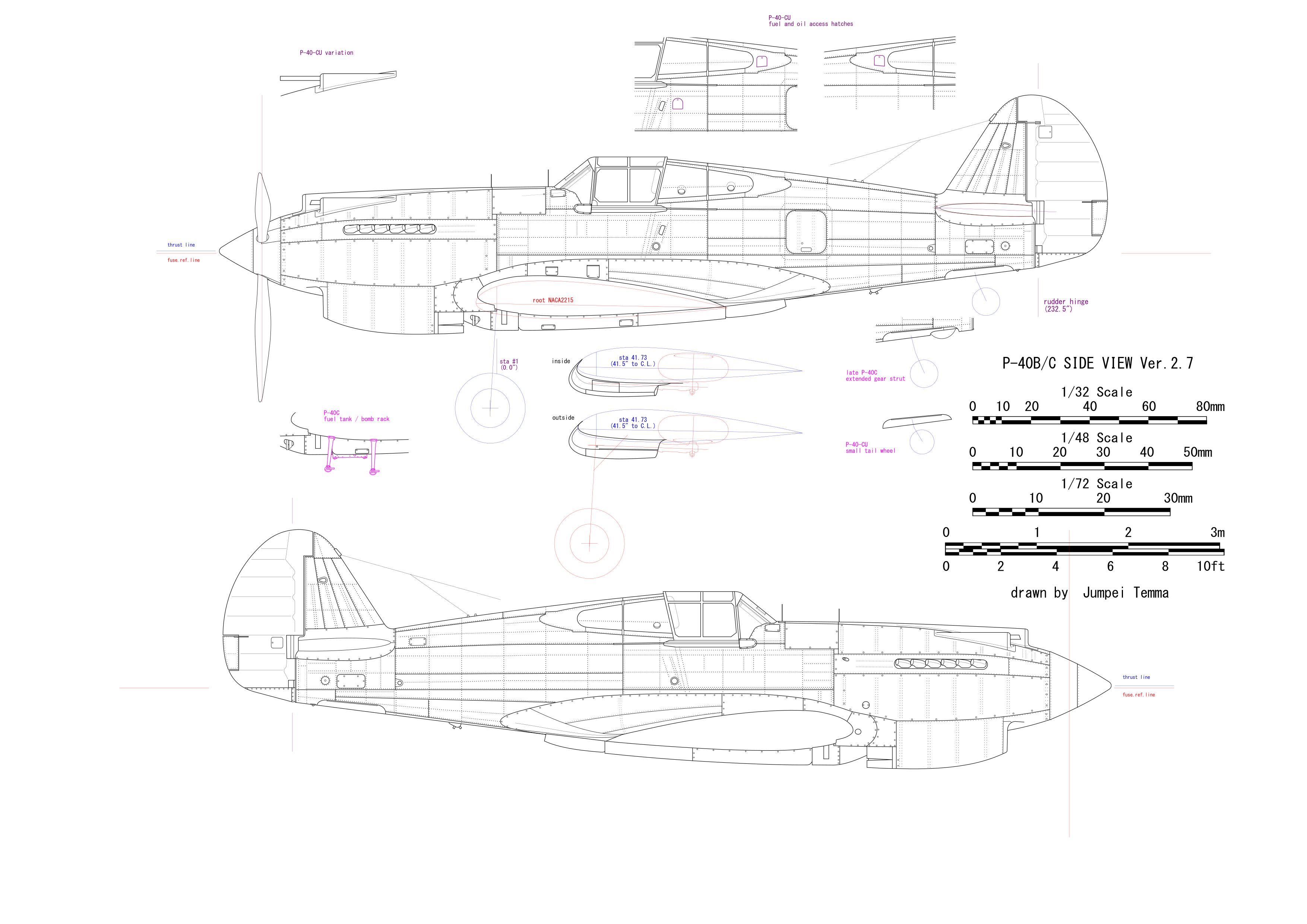
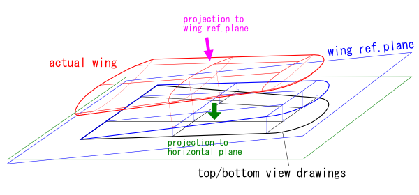
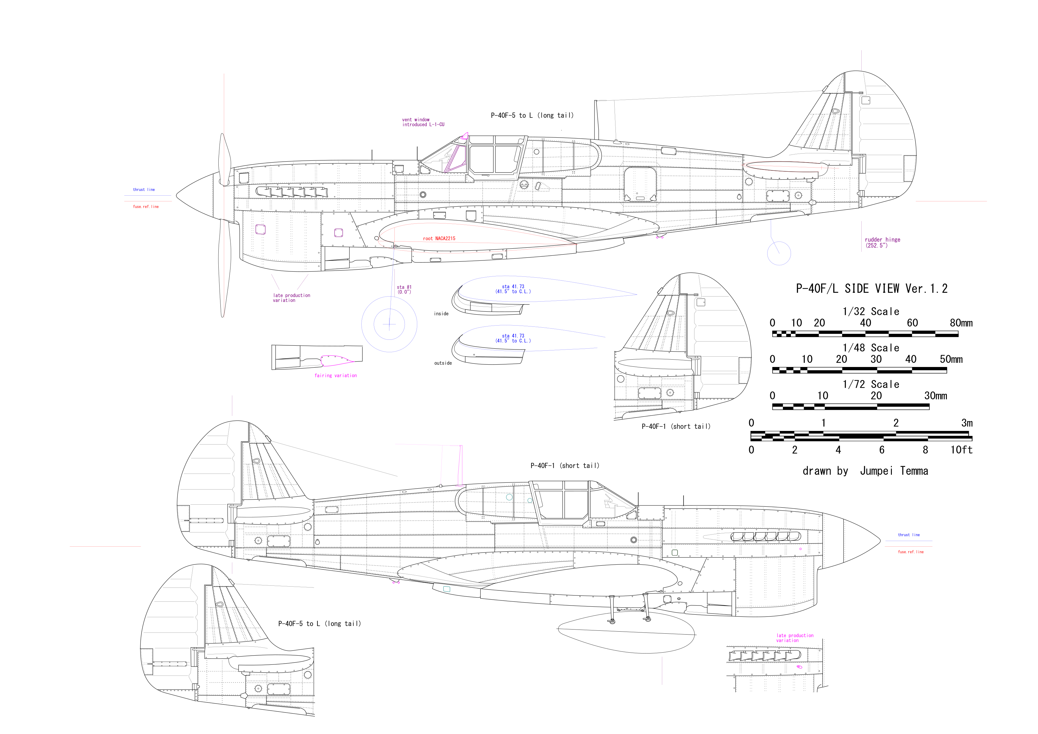
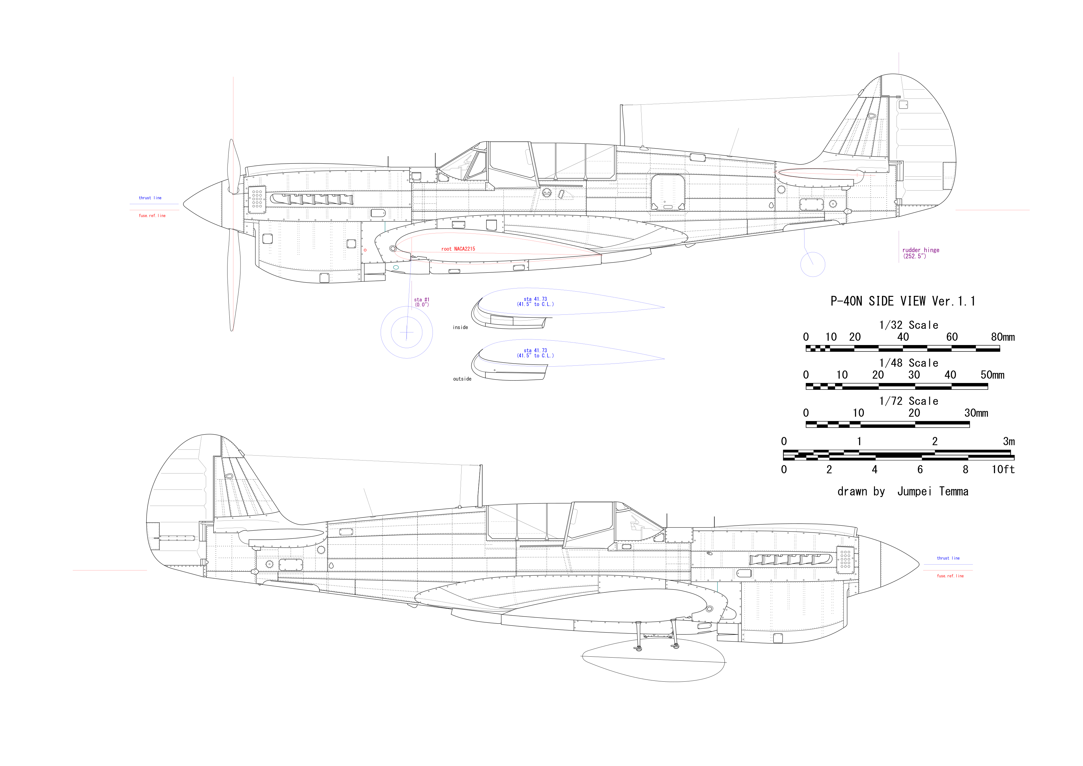
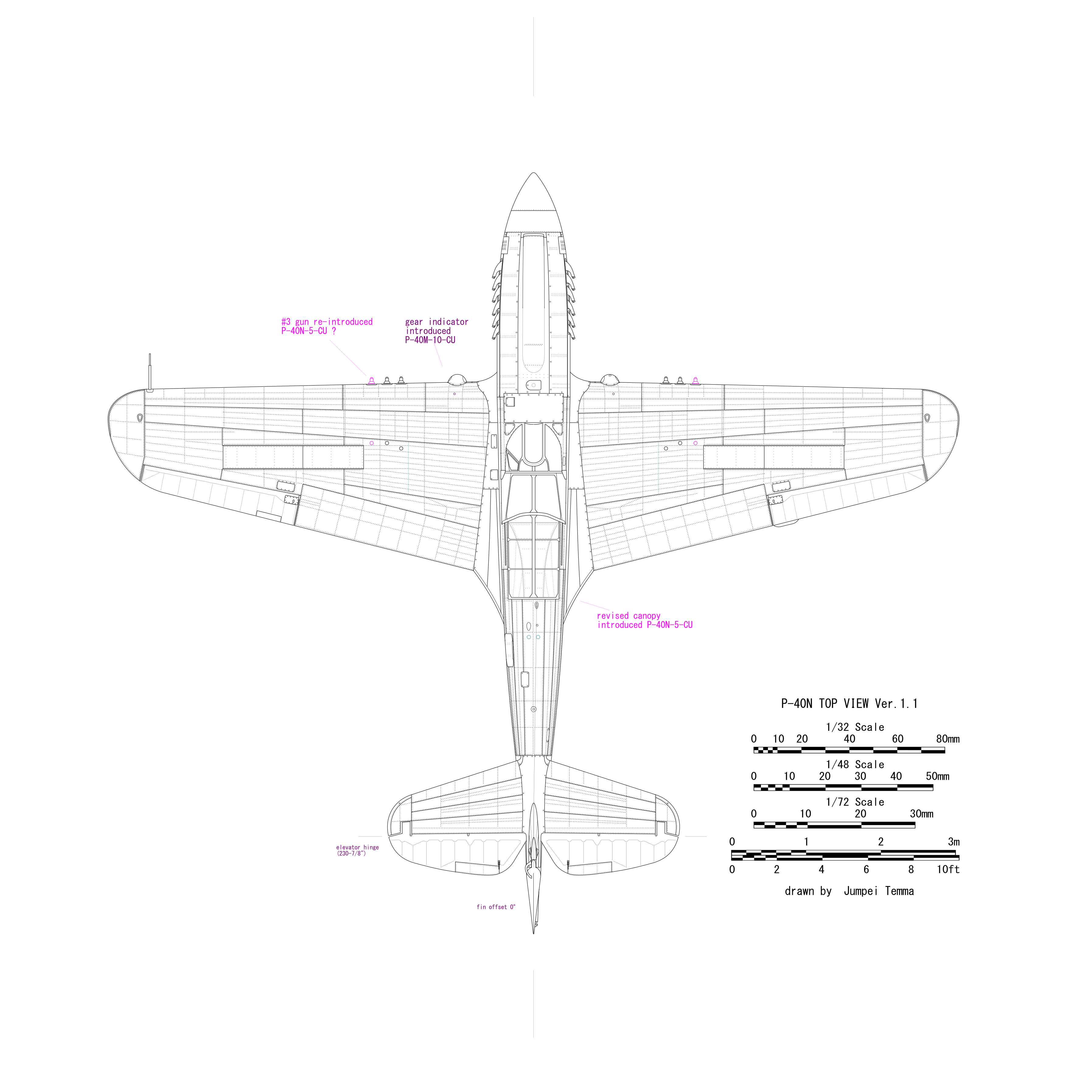
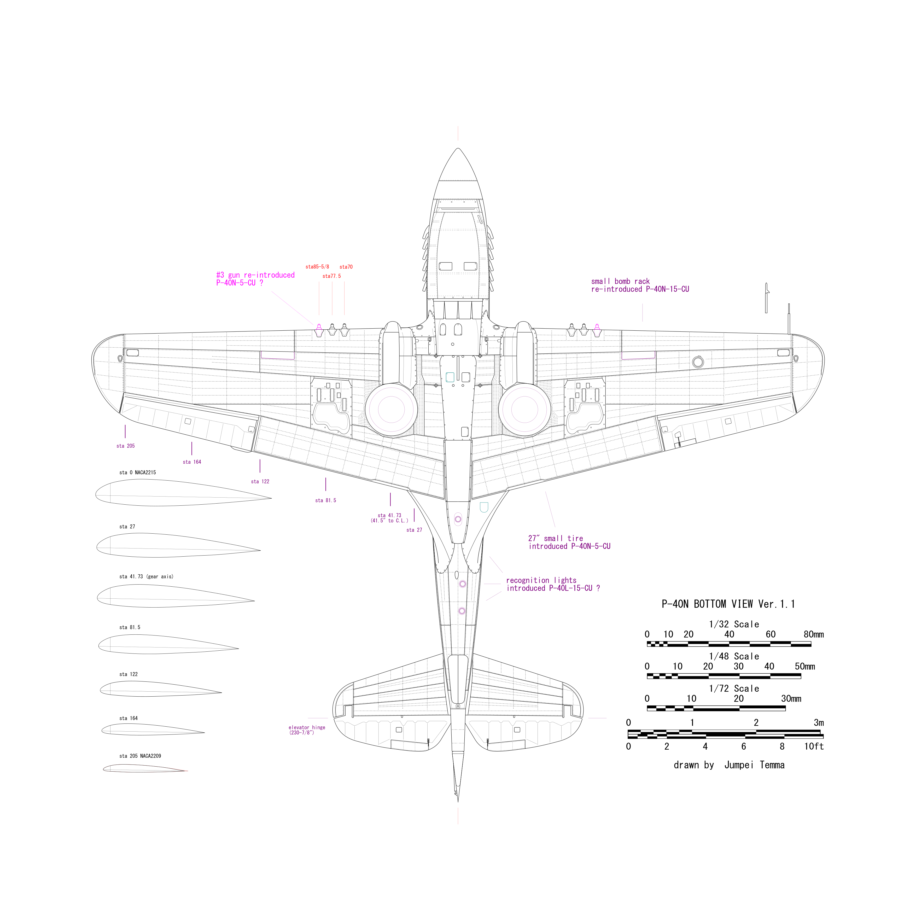
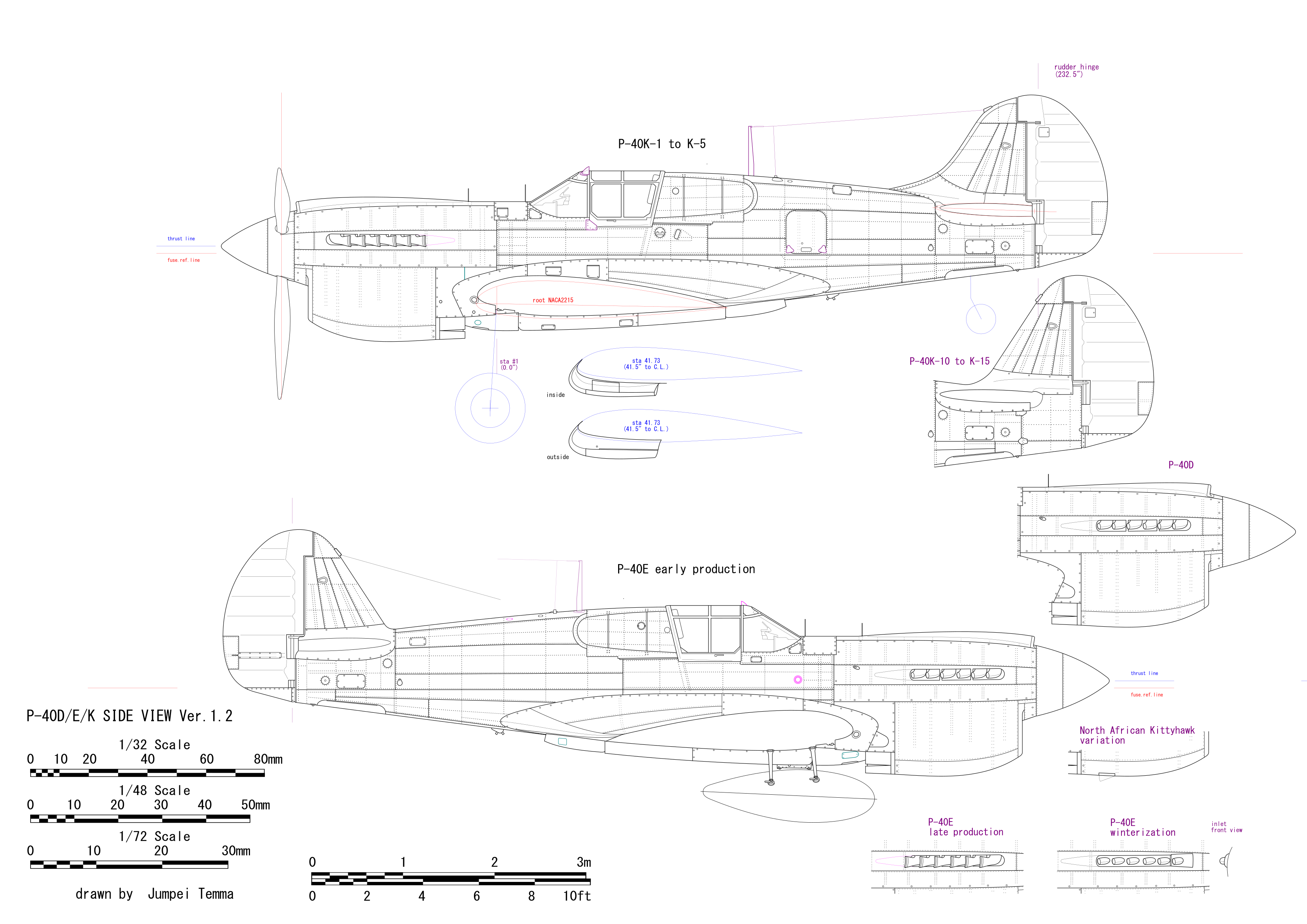
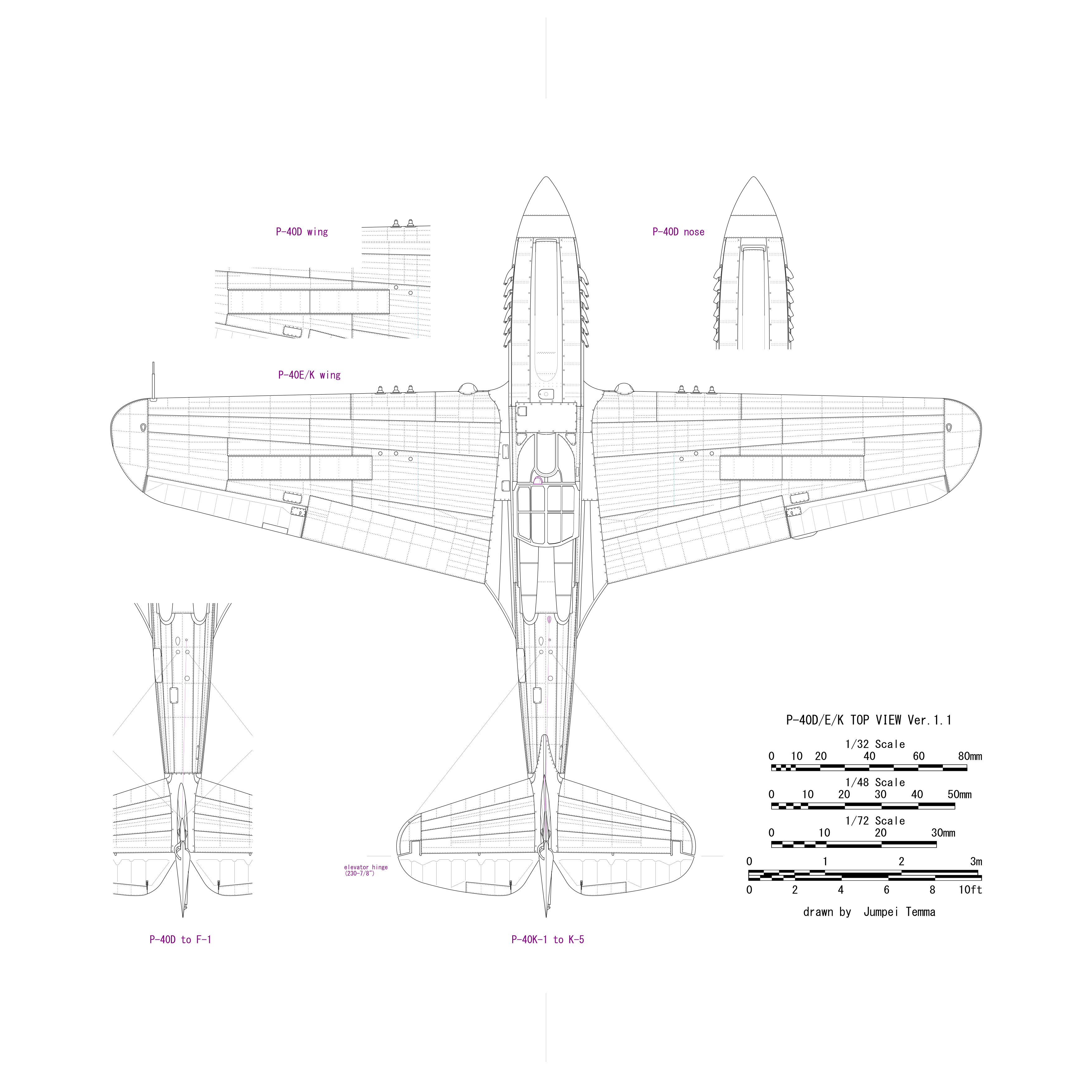
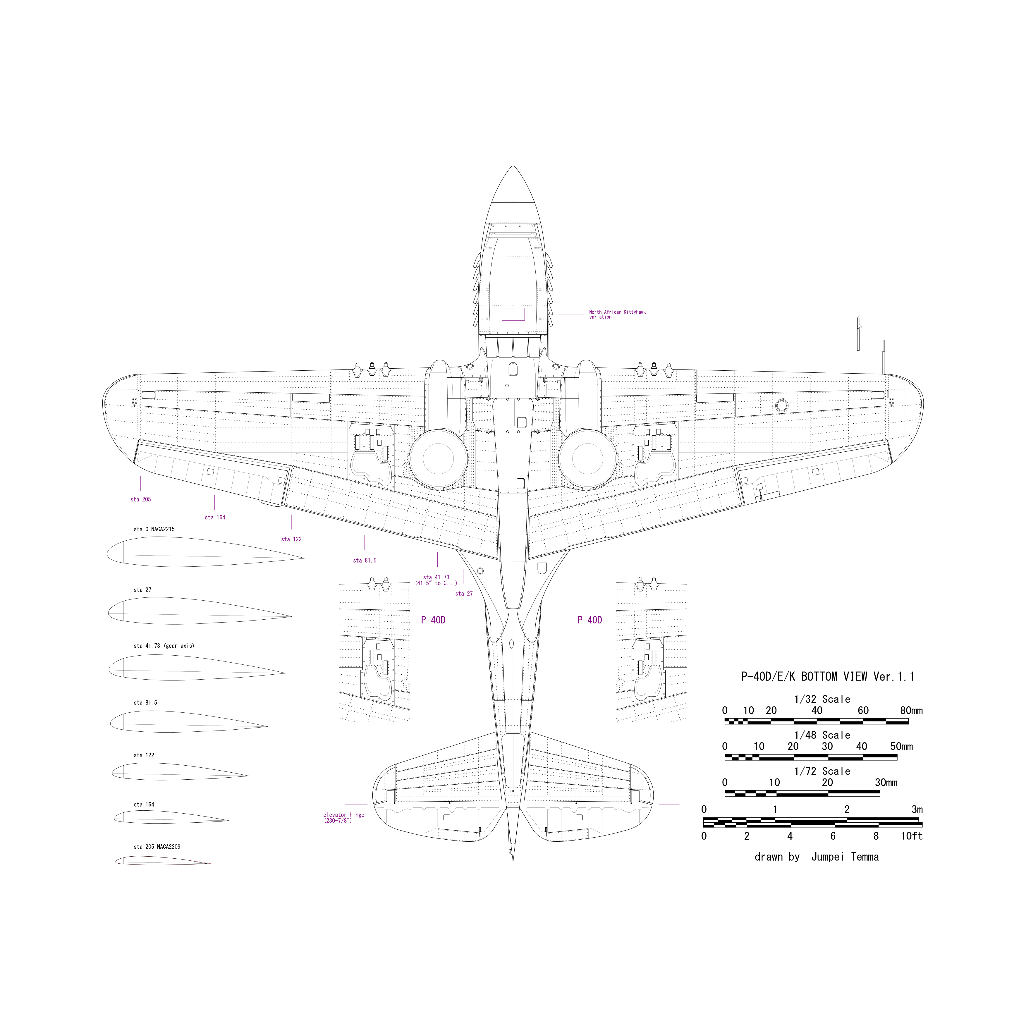
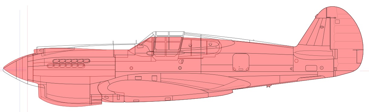
Prior to the construction, I made drawings of P-36 and P-40 Series. When I made my drawings, I used a set of Curtiss's factory drawings and the Structural Repair Instructions manual. I carefully read factory drawings and manual, checked photos of actual aircfart, then I translated them into my drawings.


Mystery of the total length of P-40 series

As for P-40 series - as well as other aircraft for example Wildcat -, total lengths described in existing reference books are not reliable. See the list below. Even the official EMI manual made a mistake.


Total Length (inches)

D&S WA IA(1) IA(2) EMI FD
P-36 342 - - - - 346.12
P-40B/C 381 - 380.56 380 - 381.6
P-40D/E 374 380.5 380.72 374 380.75(*) 380.72
P-40F-1 380.72 - - - - 380.47
P-40F-5/L 399.72 - 401.72 400 - 400.47
P-40M/N 399.72 - 401.72 400 399.72 400.72

D&S : Details & Scales, WA : Walk Around, IA(1) : In Action 1026, IA(2) : In Action 1205, EMI : Erection And Maintenance Instructions, FD : Estimation by Factory Drawings from AirCorps Library
(*) : P-40K


Lengths in the column FD of the table are based on factory drawings, and I believe these lengths are the nearest to the truth. Well, I'd explain the reason. The most reliable length is the short body model of P-40D/E/K. Each length written in general three view drawings, cowl assembly drawing, fuselage assembly drawing of factory drawings are equivalent. Values are 118-3/8" from the firewall (sta 0) to the tip of the spinner, 262-11/32" from the firewall to the rudder rear end, totaling 380-23/32" = 380.72" = 9,670 mm. The short body K model is the same as the D/E model.

It is certain that M/N model of long body Warhawk is just 20" longer than the short body model judging from the fuselage assembly drawing (the station value of the ladder hinge). Thus the total length is 400-27/32". However,the general three view of factory drawings made a mistake as total length 399-27/32". The individual lengths in this figure are correct but the total sum are not match. And I guess that the EMI manual quoted from this general drawings.

Next, as for Merlin model F/L, general three view are not included in the factory drawing. However, there are cowl assembly drawings which clearly shows that the cowl of F/L model is 1/4 "shorter than the Allison model D/E. The length of spinner and rearward fire wall are the same. Thus, the total length of Merlin model should be 0.25" shorter than Allison model.

Subsequently, P-36 (or H-75, both are the same). There is the general three rview in the factory drawings, and the total length including the spinner is described. However, it is slightly different when superimposed with the side view photo of the actual aircraft.I guess the spinner may be the reason of this diference. The rear fuselage after the fire wall is confirmed to be the same length as P-40D/E by the fuselage structure drawings. Thus the rear fuselage of P-40B is also the same as P-40D/E.

Finally, the total length of P-40B. Actually, factory drawings from "AirCorps Library.com" don't include any B/C model drawings. But according to the factory drawings of B model nose from other source,the rear end of the spinner station is -92-13/16". The length of the spinner can be calculated from side view photos. Then the station of the spinner tip is estimated -119.3". The fuselage length after the fire wall is 262-11/32" = 262.34". Thus, the total length is estimated 381.6" (rounded to significant figures).
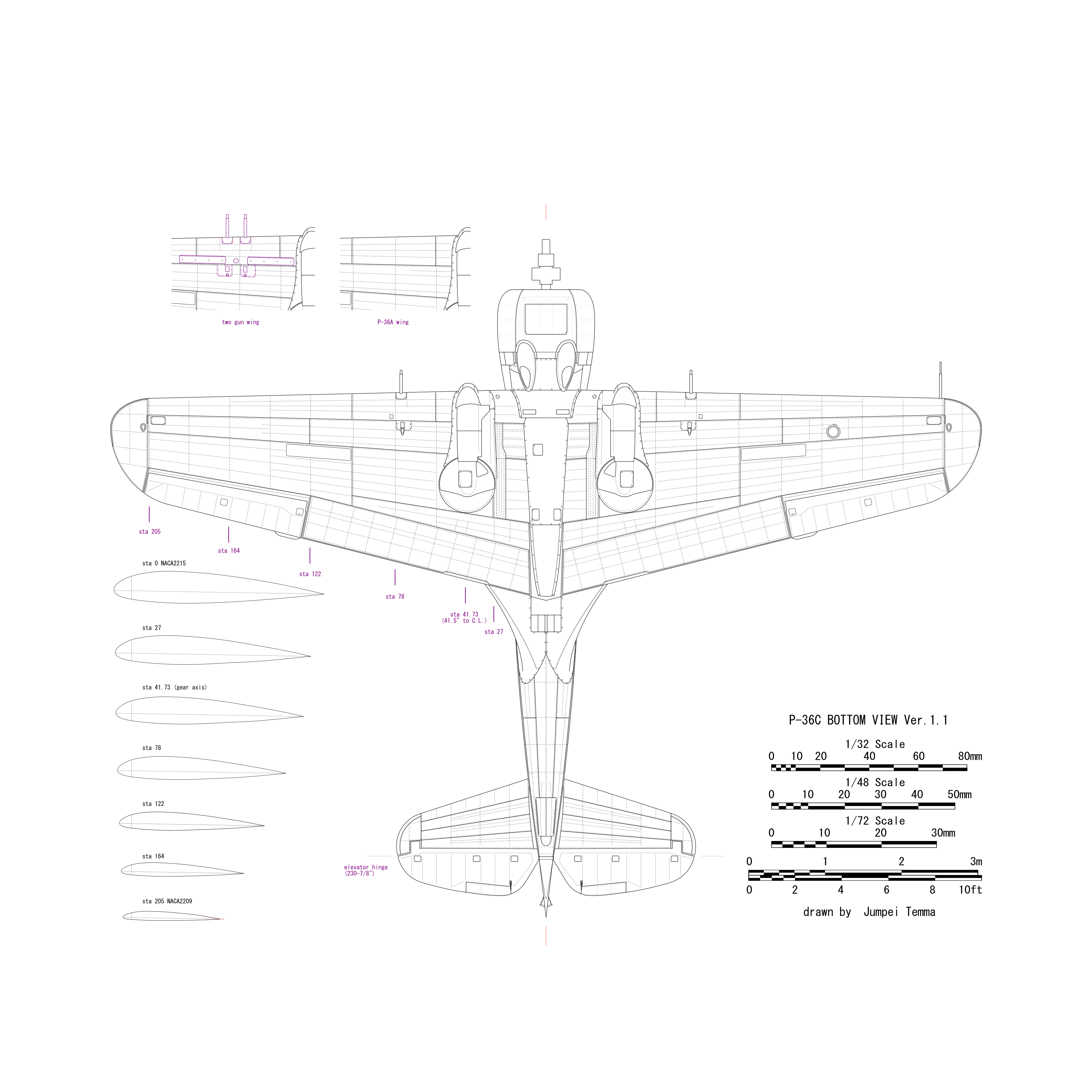

Side view drawings


  • The thrust line is higher by 1" than the fuselage reference line. Incidentally, P-36 is lower by 1.75", D and following models are higher by 3.078".

  • The side view outline is the trace of photos of actual aircraft. The red thin line shows vertual airfoil at the center line and black line shows the filet edge.

  • Airfoil : NACA2215(root) NACA2209(tip sta.197), chord:108"(root) 46-5/8"(vertual airfoil at the tip)

  • wing incidence : 1 deg. , dihedral : 6 deg. , stabilizer incidence : 2 deg.

  • The position of the wing leading edge at fuselage center line is lower by 21.5" from fuselage ref. line and forward by 9" from the fire wall.

  • The shape of the stabilizer is a trace of factory drawings. Note that the leading edge is sharp

  • The left and right frames of the slide hood are different. The port window can be opened in an emergency. The front half of the slide rail is horizontal and the rear half is inclined.

  • The rudder tub rod is different from D/E model. Some restored aircraft was mistaken.

  • Some RAF Africa Tomahawk have lower extra cooling outlet normally seen RAF Africa Kittyhawks. Believe it local Africa mod and outlet flap is fixed.


Comparison with photos

I will try to overlap with actual photographs. The photo is from airliners.net. Some portions don't mutch when you look closely. Well, I guess some of them are individual differences. The windscreen of this aircraft is more upright. It might be restoration mistake. (Note that the overlaid drawings are not the latest version.)


Comparison with E model

B and E side view are overlaped. This kind of comparion is unique to the WEB site, isn't it? Looking at individually, B model seems to be somewhat short because of the deep fuselage, but you can see that it is an illusion of the eye. Also, there are many common portions. The rear fuselage lower half and the main wing framework are the same shape from P-36 to P-40N. (Note that drawings are not the latest version.)


Cross section

I think that reproducibility of the cross section shape is highly important in modeling.


  • Coordinate values ??of the fire wall cross section of P-36 are described in the factory drawings. The shape of P-40B's firewall is basically the same except for the lower portion of the main wing. The maximum width is 39.4". On the other hand, the maximum width of fire wall of E model is 38.32". The top of the firewall is 30.07" from the ref. line.

  • The shape of each fuselage frame is trace of the factory drawings. The height is adjusted to the side viewdrawings.

  • Cross section of the cowl is estimated from photographs. Each height is adjusted to side view drawings.

  • I guess that the shape of the cowl flap base is the same as E model.

  • The fuselage machine gun fairing is lean to outside.


Top and bottom view drawings


  • The shape of the cowl is estimated from photos. The canopy width is carefully calculated from the cross section drawings. The width of the slide hood is slightly narrow at the rear. The height is the same.

  • The side portion of the windscreen is flat and spreads slightly backwards. Notice that the left and right bottom lines are not parallel. It is the same design as the Curtiss Helldiver. The curved portion of the windscreen is cylindrical.

  • The main wing is shown as projected perpendicularly on the main reference plane (see the figure below).

  • Each wing rib is perpendicular to the wing ref. plane, and only the rib of the landing gear section is perpendicular to the horizontal plane (so that it is curved in my drawing).

  • Main wing span is 447.5". Wing chord is 108" (root), 46-5/8" (wing tip), leading edge sweep back is 1°18'. Flap maximum chord is 1'9.125", span: 20'4". Wing guns are 74.5" and 83.75" from the aircraft center.

  • The position of each spar of the main wing is shown in the factory drawings. The #1 spar is located at the fire wall and it is orthogonal to the fuse ref line. The arrangement of each stringer is based on the factory drawings.

  • The curve of the wing tip consists of three circles. Horizontal stabilozer and tail fin are the same. Diameters of these circles are described in the factory drawing.

  • There is a gap between the aileron leading edge and the wing in the bottom view.

  • Horizontal stabilizer maximum chord is 42.75". The stabilizer span is 153.625". The vertical fin offsets 1.5° left.

  • The position of the horizontal stabilizer can not be matched with each figure in the factory drawing. I employs the position of the elevator hinge line of the general view. Each spar is determined by matching the rib cross sectional drawings. The #4 spar is assumed to be perpendicular to the fuselage ref line. Note that this is not the rear end of the horizontal stabilizer but at the rivet line forward.

  • With the above positioning, each spar of the horizontal stab. and vertical fin matchs each other.

  • The landing gear fairing of P-40B/C model is different D and later models. The details photo in D&S is incorrect restoration.

  • The panel line on the lower engine cowl of actual ww2 B/C model located direction of 6 o'clock. Most of restored aircraft have two lines of 5 and 7 o'clock.


Front view drawings

The front view was checked with side, top and bottom view drawings.


  • The tread is 98.125 ". It is different from P-36 and D to N model due to different tire sizes. The gear shaft center is 41.5" from a/c center. It may be the same through P-36 to N model. The tire and gear shaft are perpendicular to the horizontal plane.

  • Some panel lines are omitted in this drawings. The wing leading edge is shown with thin line. Wing guns located slightly upward to this line.

  • The upper portions of the sliding hood side window and the rear fixed window are curved. The lower portions are flat.

  • The landing gear fairing is based on the contour figure of the factory drawings. The gear shaft cover is connected to the wing by piano hinge. So the hinge line is straight.

  • There seems to be variation in the antenna wires arrangement.

  • The propeller diameter of P-36 is 120 " and P-40N model is 132". B model is unknown. I assumed as 132" in my drawing.


P-36 three view drawings

The basic structure of the fuselage and the wing is the same as P-40B. P-36 is used in the USAF. The export version is named differently, and it is confusing because there are two variant of P&W Twin Wasp engine and Wright Cyclone. So I tried to sort out as below.

P&W Twin Wasp R-1830 valiant
P-36A fuselage guns 0.50x1 0.30x1, no wing gun, 178 production
P-36C wing guns 0.30x2 wad added 32 production
P-36G wing guns was changed to 0.30x4. renamed from H75A-8 30 production
H75A-1 fuselage guns 7.5mmx2, wing guns 7.5mmx2, originally orderd by France, obtained by the RAF when France fell and named Mohawk I 100 production
H75A-2 fuselage guns 7.5mmx2, wing guns 7.5mmx2(x4 48th and later a/c), originally orderd by France, obtained by the RAF when France fell and named Mohawk II 100 production
H75A-3 fuselage guns 7.5mmx2, wing guns 7.5mmx4, originally orderd by France, obtained by the RAF when France fell and named Mohawk III 135 production
H75A-6 fuselage guns 7.5mmx2, wing guns 7.5mmx4, deliverde to Norway, Thirteen captured by the Germans who provided eight to Finland 24 production

Wright Cyclone R-1820 valiant
H75A-4 fuselage guns 7.5mmx2, wing guns 7.5mmx4, originally orderd by France, obtained by the RAF when France fell and named Mohawk IV 284 production
H75A-7 fuselage guns 7.5mmx2, wing guns 7.5mmx4, orderd by Holland, but Holland fell before delivery, provided to the Dutch Indies 20 production
H75A-9 fuselage guns 7.5mmx2, wing guns 7.5mmx4, diverted to RAF as Mohawk IV, then transferred to India 10 production

* quoted from D&S(other than A-1,-2), Curtiss manual for French Air Force(A-1,A-2)
https://web.archive.org/web/20150924021036/http://www.gc2-4.com/NSGAcouv.htm
https://web.archive.org/web/20150924021030/http://www.gc2-4.com/NMACcouv.htm


The P-36A which was first deployed on the USAF has 0.50 (starboard) and 0.30 (port) fuselage guns. There is no wing machine gun. This model was encountered Pearl Harbor attack. Only one aircraft of P-36B was producted. The following P-36C added 0.30x2 guns to the wing. P-36A and some C model had no exhaust fairing. Some C model has the fairing. It is unknown whether it is retrofitted, or removed, or introduced at the middle production of C. The spinner is step type. P-36G was ordered by Norway as H75A-8, and taken over to the US by the surrender of Norway and sent to the training unit. There are slits on the fuselage machine gun panel which is a feature of export model H75A.

Export model is different from USAF model such as fuselage gun slits, pitot tube, antenna, gunsight and so on. France was ordered H75A-1 to -4. H75A-1,-2 and -3 equipped P&W Twin Wasps, H75A-4 equipped Wright Cyclone. Each model had different wing guns. H75A-1 and -2 had no fuselage gun slits. Due to the surrender of France, part of them was handed over the RAF and was named Mohawk. The spinner of them was mostly step type. Some late model has shell shape spinner. Part of H75A-6 was sent to Finland. Cyclone engine model was also seen in the Finnish air force but its history is unknown.

  • According to the factory drawing, it is 29-7/16" from the cowl tip (excluding machine gun fairing) to the firewall, and 291.78" = 7,410mm from the firewall to the trailing edge of the rudder. The thrust line is 1.75" below the fuselage reference line.

  • The demarcation line between the windscreen and the fuselage is more simple than P-40B. For comparison, as for the P-40B, the fuselage top skin rearward of the small access panel turns upward along to the window. Also the details of the slide hood such as the position of the central vertical frame and corner cutting are different.

  • Front and rear tires are smaller than P-40. The front tire is 27" in diameter, the rear one is 10.5". Front and rear gear covers and their fairings are also different. Propeller diameter is 120".

  • Front three of the fuselage gun slits on the export type H75A open forward and the remaining open rearward. Also, a small rectangular panel can be seen on the starboard accessory cowl (unknown whether it is in all models). However, there is no slit and no blister as for H75A-2. French ordered models equipped the tall antenna mast. The antenna wire is not connected on this mast but the same arrangement as the USAF model.

  • According to a certain forum (URL is shown below), panel lines of the rear fuselage are similar to P-40B. Closeup photos in D&S are this type as for the latter production model.

    http://www.britmodeller.com/forums/index.php?/profile/4702-hbbates/content/&type=forums_topic_post&


  • The width of the accessory cowl calculated from coordinates table of the factory drawings is different from the width measured from photos of actual aircraft. I adopt the latter. Because I'm an actualist.

  • It is unknown whether the fuselage machine gun panel is divided into three like P-40B.

  • The number of main wing stringers is slightly smaller than P-40B. The shape and location of 7.5mm machine gun panel of H75A-3 and -6 are the same as P-40B/C.

  • The position of the antenna wire is different from P-40B.

  • French H 75 with twin 7.5 mm fuselage guns staggered. British H 75 with twin .303cal fuselage guns are inline.


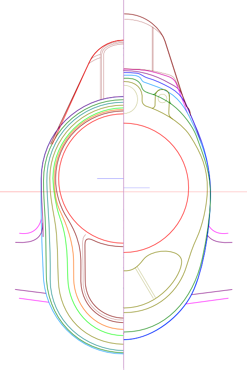
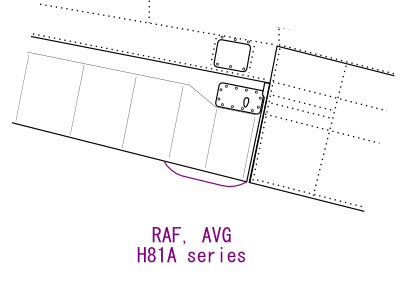
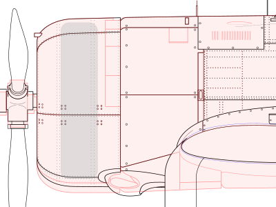
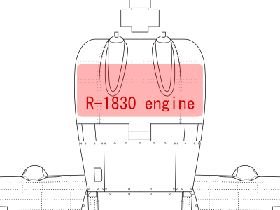
The engine cowl top view shape was drawn as to take the necessary clearance from Twin Wasp R-1830 engine (diameter 1,220 mm). When it was drawn as the coordinate table of the factory drawing, the side line from the engine cowl to firewall did not connect smoothly.


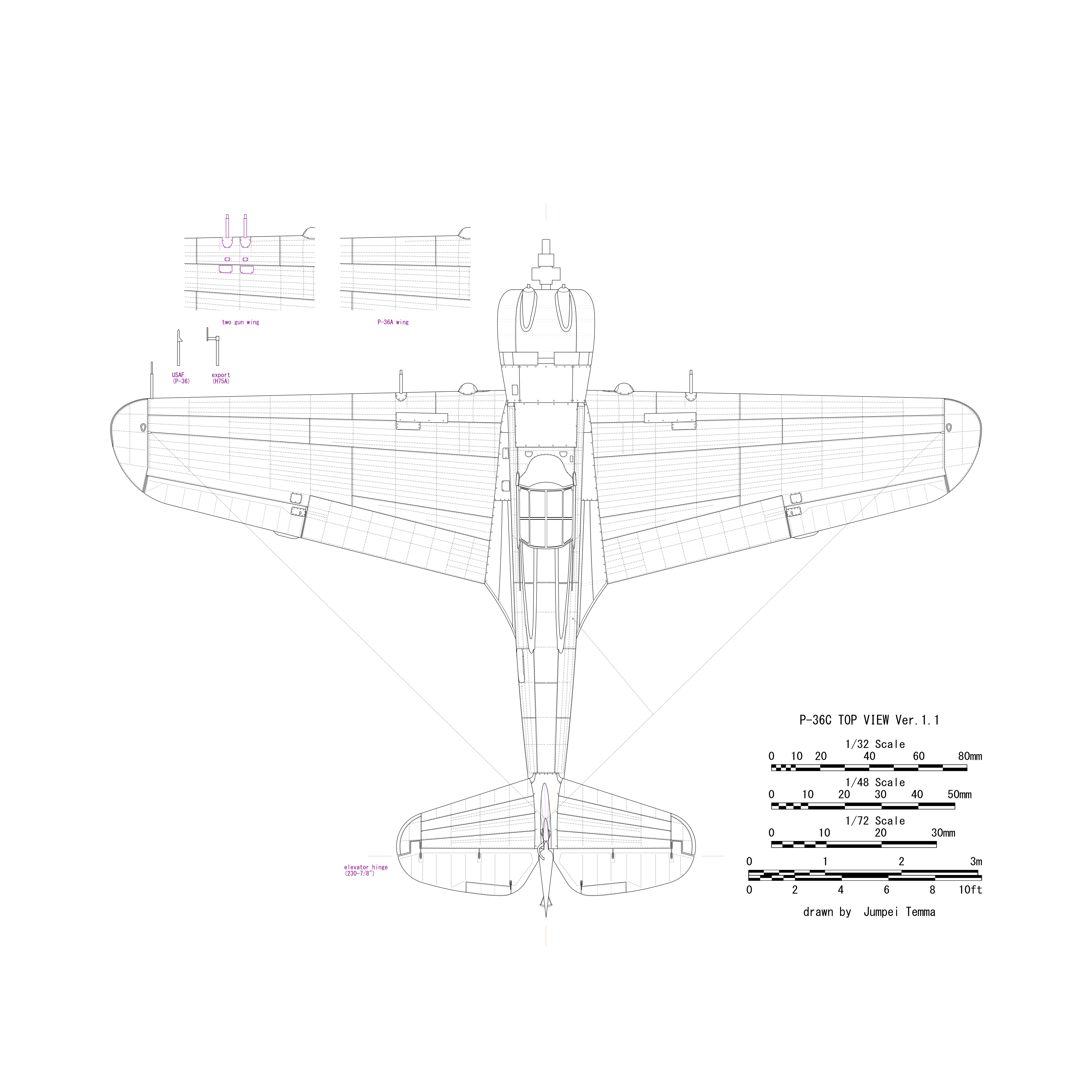
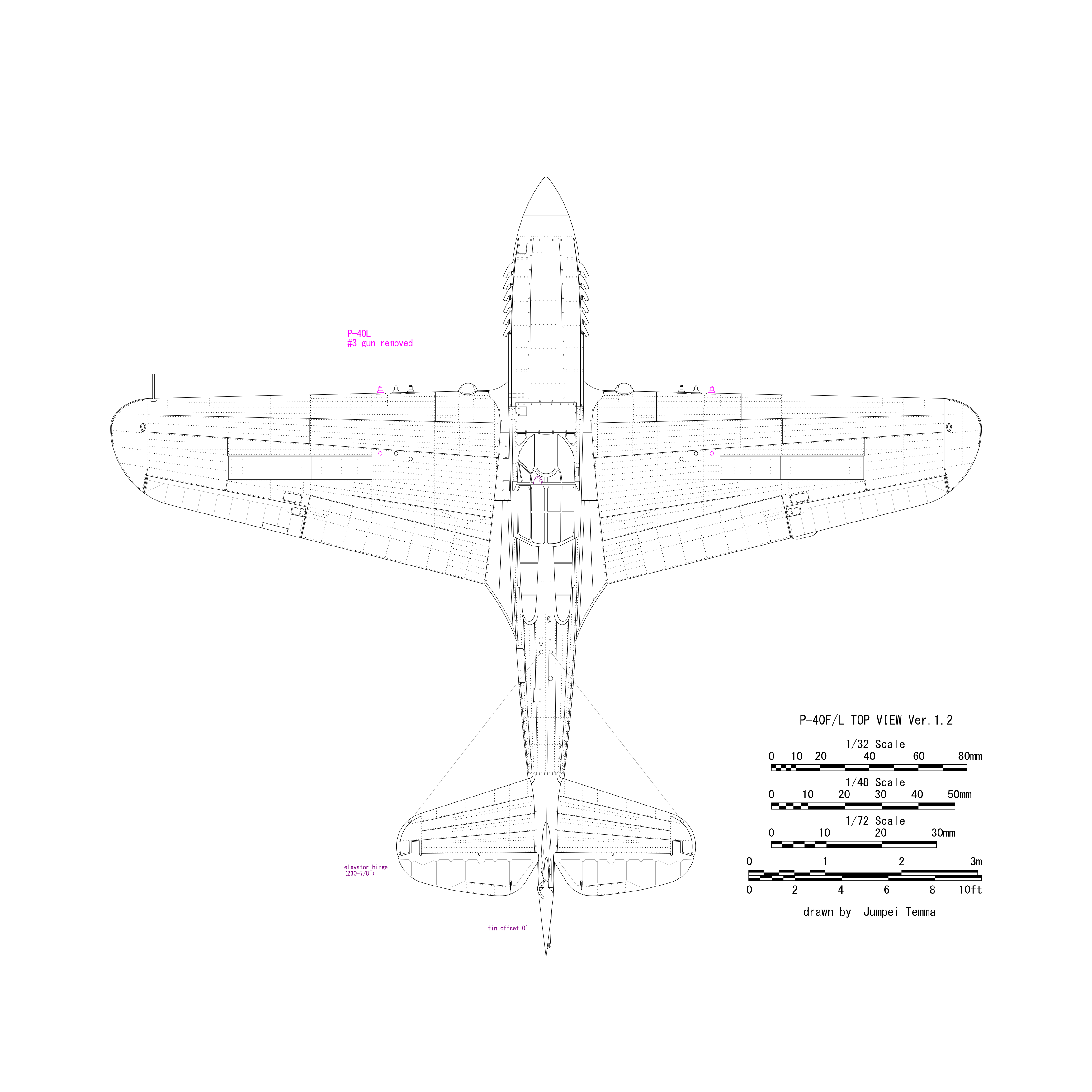
The horizontal stabilizer rear end line is different from P-40. The hinge position is the same, the elevator of P-36 is extended forward. There are two curved stays that support the hinge tube of the elevator.


  • The patch on the outer main wing in the bottom view is a cover of bomb rack.

  • Cross-sectional shape and dimensions of the firewall are adjusted to accessory cowl coordinate table. Of course, it is the same shape as P-40B except for lower fairing. Basically the fuselage cross section shape rearward the firewall is the same as P-40B/C.

  • The shape of the exhaust pipe fairing in the front rear view is less accurate. The drawings of gear cover and fairing are contained in the factory drawings. However, it is not 8.perfectly match to photos of actual aircraft. The tire is smaller and the tread is narrower than P-40. The position (height) of the main wing is the same as P-40. The wheel bay is smaller.

  • The one gun and two gun Hawk 75 81 wing has the gun mounted different. One gun barrel is above wing LE, two guns barrels are below wing LE (believe it relates to ammo box above on one gun below on two gun)


■ P-40B/C trivia

Six exhaust holes of Allison engine are not equally spaced. The space between the third and fourth is a little wide. If you carefuly look at photos of actual aircraft, you can notice the exhaust pipe interval is different. It is not only B model, but also D and subsequent model. On the other hand, Merlin engine is equal intervals of 6-1/16 @ 5. Well, it is about 0.01" in 1/48 scale.

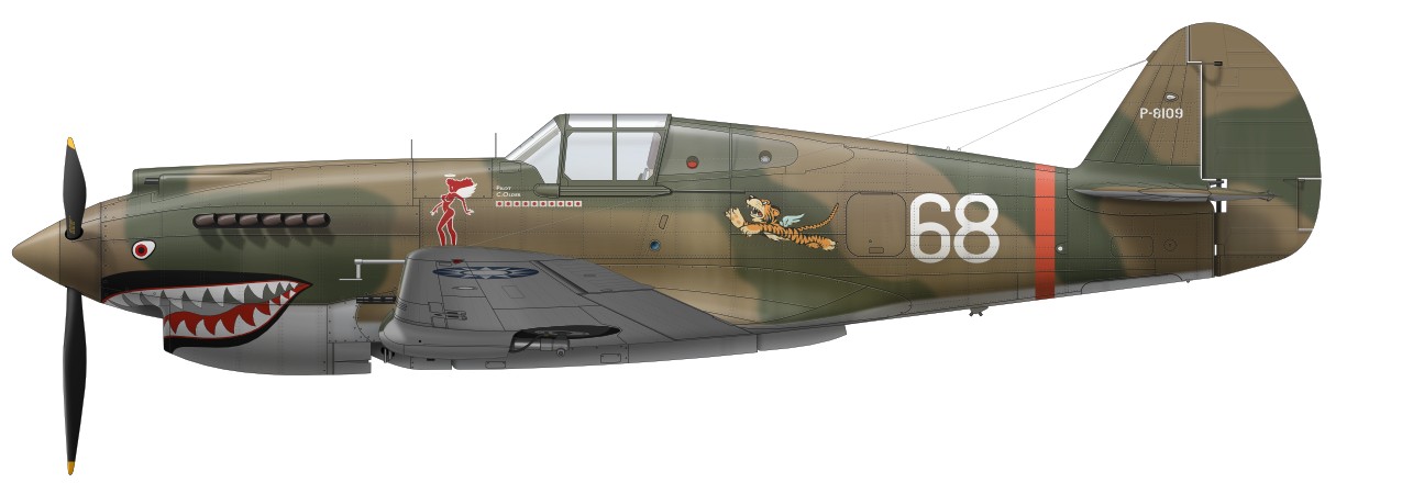
Port Aileron tab of the RAF Tomahawk including Flying Tigers's H81A-2 is fixed type. On the other hand, the USAF model is movable. In the late production of C model, the tail gear legs is longer, and the rear end is cut off.


Cyclone Hawk

Next drawings are Cyclone engine models. But there was not enough data to make the accurate drawing. Although there is a reasonable good aerial photo showing side profile, there is no good photo of top view, details (especially the lower side). So my drawings are close to imaginary figures. There are many unknown parts on the underside. So I didn't make bottom view drawing to prevent from misunderstanding. Perspective errors of side profile aerial photo are corrected, then it was traced. Thus I think the outline of side view drawings is and the outline of the side view adequately accurate.

  • There are different engine mount engine location fix gear R8120 Hawk 75 vs retracts. The thrust line of retract gear model is 2" below the fuselage reference line. The fix gear model is 1" below.

  • I assumed the fuselage gun position is the same as P-40B. Incidentally, the P-36 is thought to be the same gun position, but the fire line may be inclined slightly upward.

  • Panel lines, exhaust pipe, fasteners are not perfect. I only protted what I could see in photos. The light blue line at the lower part of the wing means its existence is uncertain. The oblique line under the accessory cowl was assumed from fastener holes of the photo. The distance between the left and right exhaust pipes is the same or slightly wider than that of P-36.

  • The position of the engine and the propeller is assumed from these positions of the FM-2 Wildcat. The top of the accessory cowl (from 11 o'clock to 1 o'clock) is connected to the gun access panel in a plateau shape with maintaining a large curve of the engine cowl cross section. 11 o'clock and 1 o'clock are bent with a small radius corner. This rudius becomes large as it goes forward. 2 o'clock, 10 o'clock of cross section might be a slightly sharp line. I guess the front lower visibility might be considered.

  • The cowling opening seems asymmetric vertically with respect to the propeller axis and the lower half is large. There are upper and lower air ducts connected to the supercharger and the oil cooler with similar as P-36. So the engine cowl is a vertically long. Duct entrances can not be seen from the front.


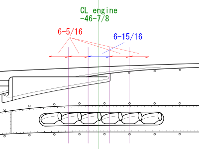
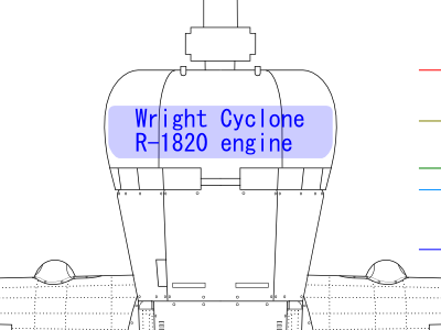
The maximum diameter of the engine is in front of the cylinder and the rear half is narrow.

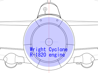
The diameter of Cyclone R-1820 engine is 1,378mm. There are spaces of air ducts at the top and bottom. The machine gun should pass between the cylinders.

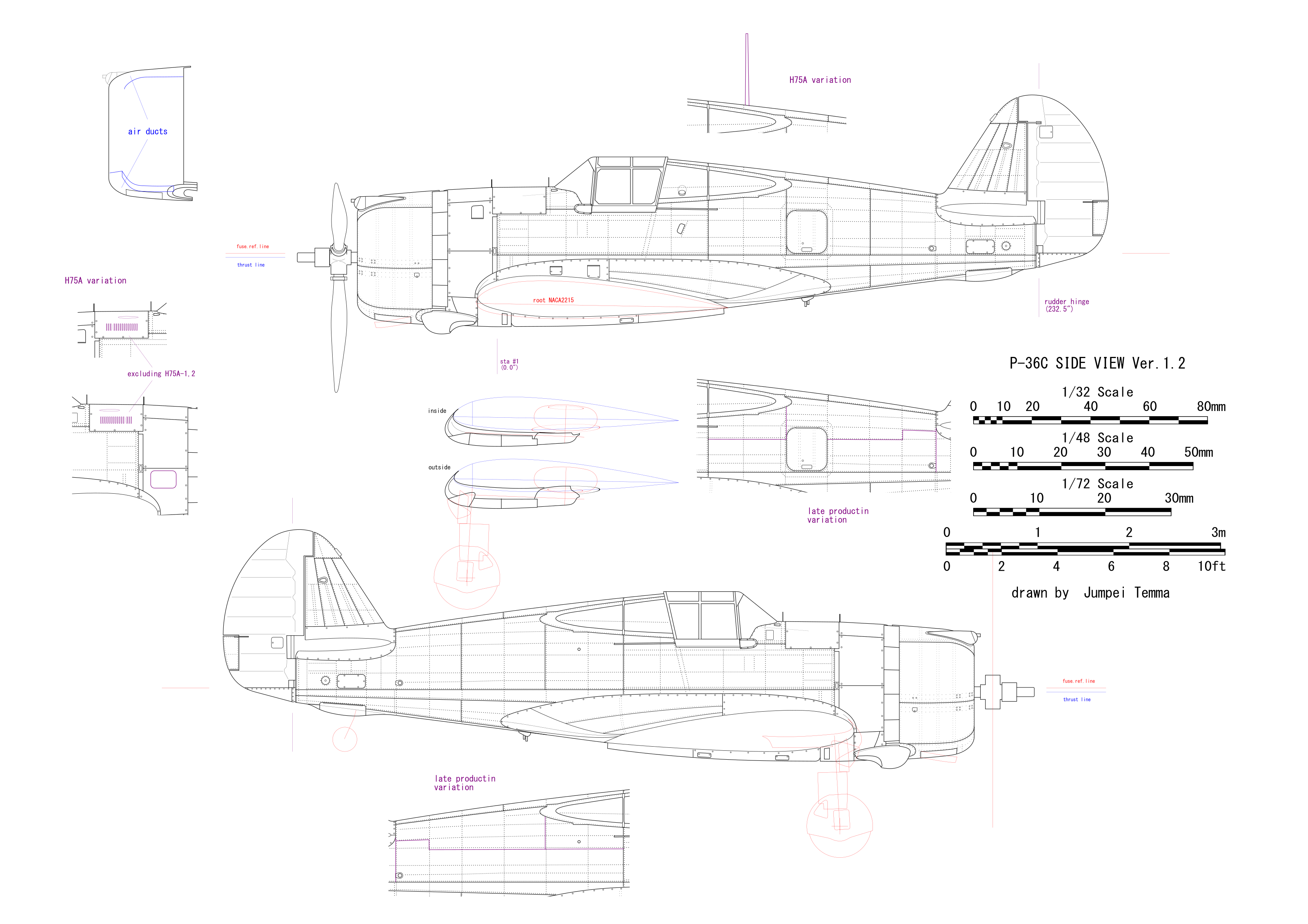
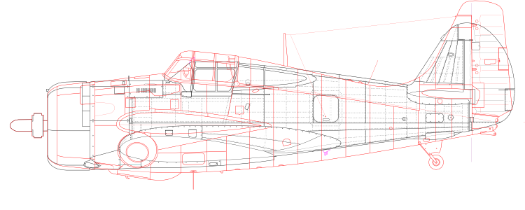
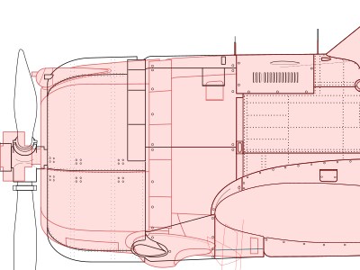
It is compared with Twin Wasp P-36 in the side view. The total length due to engine differences is not so different as Wildcat.

I guess that the accessory cowl must be wider than P-36.


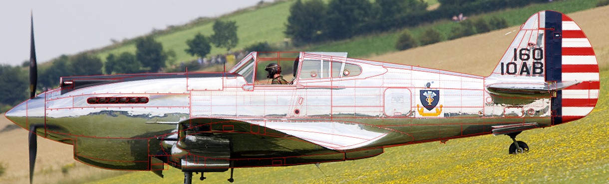
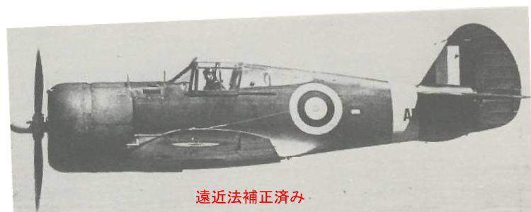
I'd show side view photo which was errcorrected perspective error. Sources are reference -39. The step of the silhouette is not the step of the fuselage but the gear fairing. Don't make a quick judgment. I'd also try to overlap with FM-2.


B/C trivia part 2

  • According to the "Aircraft Pictorial series" Warships Publishing, the elongated rectangle in front of the main wing lower aileron of P-40-CU and P-40B/C is the storage of the parachute flare bomb. Small bomb racks are mounted on similar rectangular (slightly different positions) on the lower wing of P-36/H-75A. Flare and small bomb racks may be interchangeable?

  • The temperature probe is mounted in front of the port flap. It is too small in the drawing to recognize, but the front half is a coil, three rectangulars are fixture , the rear half is a thin pipe and the front and rear ends enter in the wing. Detailed pictures are in the Aircraft Pictorial.

  • Three types of tail gear can be confirmed. The tail wheel of P-40-CU is the small diameter (10.5") the same as P-36, and the gear shaft is shorter than P-36 because there is no bulge on the gear cover. The tail wheel of many of P-40B/C is large (approx 12" in the photo), and the gear shaft is extended a little.

  • In addition,the gear shaft of the late production of C model is extended more. Along with this, the fuselage opening widened backwards, and the cover was cut off to clear the tire. However, the extension of 6" described in the Aircraft Pictorial is not consistent with the photo. I assumed approx 4" or 4.5". The diameter of the tail wheel is the same as the second one. E and subsequent model have long shaft as well, but there is no cut off of the cover. I guess the retracting mechanism was redesigned.

  • Bulletproof glass inside the windscreen is not attached to some aircraft. The small square glass in front of it is the reflector of the gunsight and the main body of the gunsight is placed under the instrument panel. Bulletproof glass is mounted inclined slightly downward to the right. This seems to be a measure for not overlapping the projection image of the reflector. If it is completely depicted in a model, it looks like poor craftwork.

  • This bulletproof glass is hung on two thin rods passed along the windscreen inside with metal fixture. In addition, a rod is horizontally passed over the inside upper part of the windscreen rear frame. This rod is not visible in the side view and the top view drawing. It is drawn in the front view. The two lines drawn on the windscreen glass are glass joints.

  • As for the P-40-CU model, the fuselage fuel tank and the oil tank filler port are different. Also, there is no formation light on the left and right of the fuselage center. After B model, the fuel and oil caps is transferred to the inside of the port rear quater window, and round holes are opened in the glass. Some P-40-CU has long fuselage gun blast tubes.

  • Also add a picture of C type tank / bomb rack. The stay of the tank / bomb looks perpendicular to the wing surface plane when viewed from the side. Also, thin rods that adjust the angle of the stay penetrate the fairing and are fixed on the fuselage center line on the lower surface of the wing. In other words, when the fairing is removed and viewed from the front or rear direction, the stays and rods form a W shape. In the bottom view drawings, only the stay mount base and the fairing hole are shown.

  • The position of port and starboard navigation light on the tail fin slightly shifts back and forth. This is the same arrangement from P-36 to P-40N.


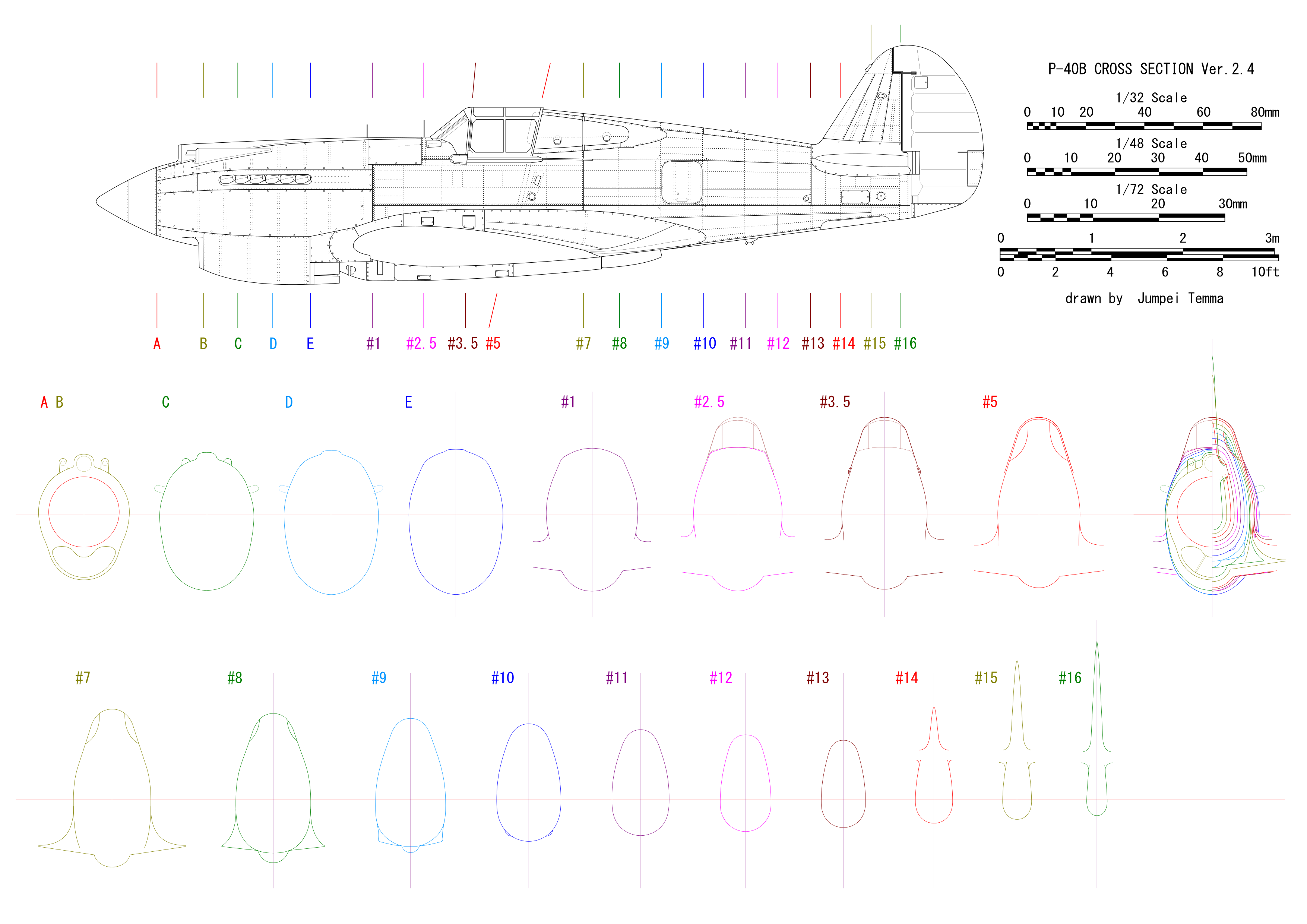
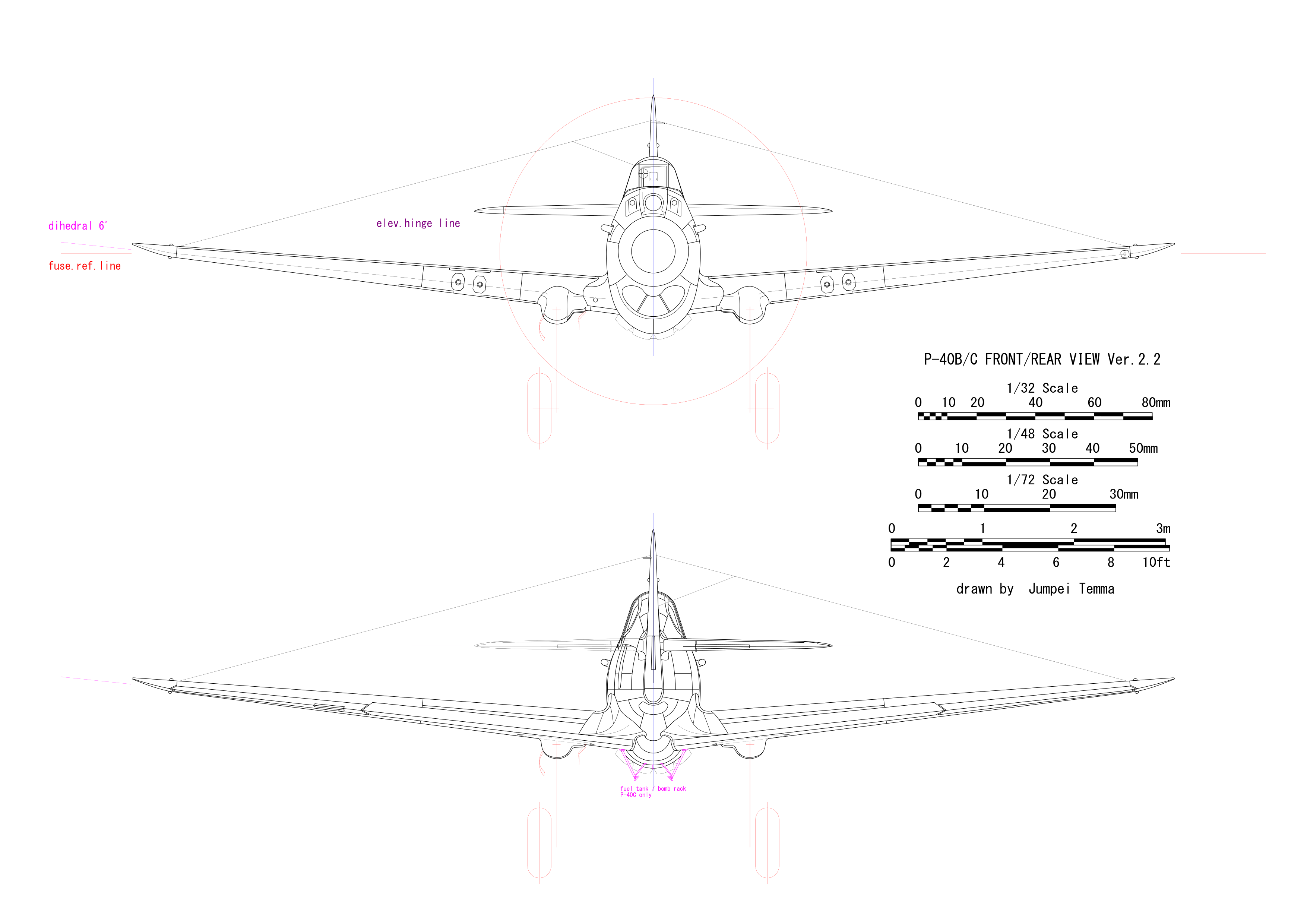
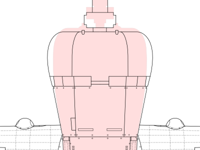
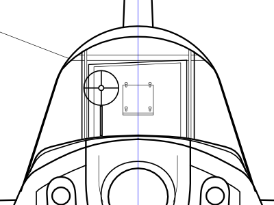
Expansion of front view. Bulletproof glass fits into a metal frame. The metal fixture is omitted in this drawing.


Fixed gear Hawk drawings

There is not enough material to make the correct drawing. So these drawings of the fixed gear are almost the imaginary picture. There is a reasonable good photo for the side view of the gear fairing. But, there is no picture from the front. So, the front shape and the location of the gear fairing are not so accurate but imaginative.

Anyway, I list up fixed gear Hawks below.

H75M fuselage 0.50x2 wing 0.30x4 ordered by China 30 production
H75N fuselage.50x2 wing 0.30x2 ordered by Thailand production number unknown, some aircraft mounted 23mm gun under the wing
H75O fuselage.50x2 wing 0.30x2 ordered by Argentina 29 production, additional 20 built in Argentina

H75H, Q are both only 2 were producted. H has different shape gear fairing, curved windshield. Some references describe that H75Q has retractable gear.

  • At first, I thought that the engine cowl side shape is the same as the retractable gear Cyclone Hawk, the photo (O model : according to caption) of ref.-15 is different in the lower line, and there is almost no clearance with the engine. Is the duct to the oil cooler narrow or located between engine cylinder? As for M and N model, the impression of photos looks like the same cowl shape as O model.

  • In the above mentioned photo, there are three cowl flaps on one side. However, since it seems like "None" in the existing N model at Dong Muang Airport in Thailand. And also, O type of Argentine Air Force in LIFE color photo looks "None".

  • The gear fairing of M model is the same as H model. The center of the fairing is narrow. The flat windscreen grasses, step shaped spinner, etc. are considered to be the same as N and O model. According to the D&S, there are two fuselage guns on N and O model. But it looks only port gun in photos of actual aircraft.

  • The gear fairing shape is from the photo of ref.-15. At first glance, the tire looks larger than the retractable type H75, but considering the error of the perspective (the camera position is close to about 30ft from the tip of the wing), it is understood that the tire is the same size. Panel lines and details are not clearly seen in photos.

  • The front view shape of the gear is highly speculative. It is assumed that location of the gear mount is the same as the retractable gear. From ref.-16, the lower poition of the gear shaft is thought as a curved cantilever fork. However, the offset amount is unknown. There is also an oblique reinforcing member similar to the retractable gear.

  • Many aircraft removed the exhaust pipe fairing and the wheel cover. The starboard drawing shows such situation. Some aircraft are fitted with wide low-pressure tires, in which case the removable wheel covers is more curved.


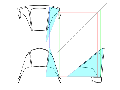
Black lines are fixed gear model, red lines are a retractable Cyclone model, grey is a Cyclone R-1820 engine of fix gear model.


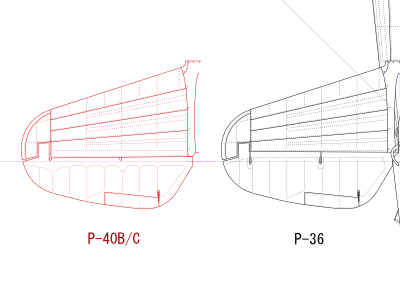
The shape of the windscreen composed of flat glasses is determined as follows. First of all, I considered a triangle (light blue) with extending the front, back, and bottom sides of the side window. The angle of inclination of the front window is the same angle as the curved glass type. It can be seen from the photo of the actual aircraft. Then I confirmed with a supplementary line of 45° so that three vertices of the triangle do not contradict each other in each drawing. Since the shape of the windscreen rear frame is the same as the slide hood, the two points of the triangle are fixed, and forward point is moved and searched where the shape of the front window looks like photo of actual aircraft. The result is shown below. It should not be "drawings which can not be built". Since the side window is narrowing forward, the top view shape of the lower fairing is also different from other models. The fixed gear type might be planned knockdown production and easy to manufacture.


P-40F/L side view drawings

First of all, I review these models. There is almost no difference between F and L model. F-1 has a short tail, F-5 and subsequent models have a long tail. L model is a lightweight variation, the external differences from the long tailed F are that machine guns are reduced four and small windows are attached to the port side of the windscreen. However, there are various parts in internal details, and there are also uncertainties as to the timing of introduction. So you had better to confirm in actual aircraft photos when you build your model. My drawings show early F model as the starboard side and late L model as port.


  • The outer shape of the upper half of the engine cowl and panel lines are basically the same as those of the short nose Allison model (P-40D to N) excluding the upper air intake. However, the cowl length is shorter than Allison model by 0.25". The fuselage rearward the firewall, main wing and tail fins are basically the same.

  • The slit for exhausts of F/L model is raised forward in the side view. Theis is the consequence of the tapered cowl and the exhaust pipe extending downward from the engine. The slit of Allison P-40D to N model is the same (be aware the lengthwise position is different). On the other hand, P-40B/C's slit is dropped forward. This difference is come from the direction of the exhaut pipe in front view.

  • The thrust line of F/L model is 3.078" from the fuselage reference line. This is the same as Allison D to N model. The middle of six cylinder rows of the Merlin engine is 56.75" from the firewall, and the interval of cylinders is 6-1/16".

  • Two small square access panels on the port radiator cowl are introduced at middle production of F model. Also, the starboard surplus cooling liquid discharge hole is a simple hole at the early production model. And in the later, it changes to the teardrop shape blister like B model.

  • P-40F-1 has no antenna mast, and antenna wires are stretched from the both wing tips to the fin leading edge. The other upper fuselage is the same (probably) through early F to late L. The two left and right circle panels behind the navigation light are connections of the IFF (?) antenna stretched to horizontal fin tips. The starboard round hole rearward of them may be the signal flare projector.

  • There is the small square detachable panel on the lower rudder rearward the hinge on P-40B/C. But it isn't seen in F and subsequent models. I guess this panel is removed after the F model.


P-40F/L cross section drawings

  • I think that the upper half of the firewall cross section is a true circle, the center of this circle is located at the thrust line, and the radius is 19.16" ( fuselage maximum width ÷ 2 : written in the N model EMI manual). These are consistent with the factory drawings of the fuselage etc. Incidentally, as for the B/C model, the width of firewall is 19.7". Thus the fuselage of B/C is wider than D-N.

  • The intake opening of the jaw is quite narrow. From there, the cowl rapidly spreads to the maximum width. When you compare the cross section and side view, you may find this fact. The majority of existing drawings and aftermarket parts are too wide.

  • The cross section shape of the lower half of the fuseage is different form B/C as for from the firewall to sta.5. The width of the wing joining attachment is the same (or nearly the same), but the angle of rise is different.

  • The lower half of the fuselage after sta.6 is the same as B/C in external shape. However, the inside structures such as frames are different. These frame parts are not common.

  • The extensions plug of sta.16 - 18 are not parallel like as FW190D but tapered. The height and width of sta.18 frame are smaller than sta.16.


It is interesting to compare cross sections of F/L and B/C side by side. It can be seen that the front projection area is considerably different. Please note that the same color does not represent the same cross-sectional position.


F/L top and bottom view

  • P40-E and -F have different fin offset. F model is 0 deg.

  • Although the outer gun is removed due to weight saving in the L model, the access panel on the underside remains unchanged and the shell exhaust holes are not patched as well (probably). The muzzle is patched with the panel without fairing. It is unknown whether the small circle hole on the upperside is removed (I guess unchanged).

  • The half-ball shaped cover at the muzzle fairing is designed to move freely according to the adjustment of the firing line. Something like a eyebrow. This is similar to the P-36 fuselage gun and P-51D. I made drawings as the center position.

  • The amunission box is completely perpendicular to the fuselage ref. line. The difference in width between the inside and outside panel can be understood by considering that the amunission box of first D model which has two guns is wider by one wing rib.

  • The short tail F has no antenna mast and the long tail F and L has this mast. However, there are some irregularities depending on the nation and theater. For example, as for the French Air Force in North Africa, the antenna mast is retrofitted to the short tail model. This mast is offset to the starboard, while the anti collision light is to the port.

  • There is confirmed that some aircraft have the small light and D-shaped panel on the bottom of the wing fillet. But it is unknown whether all of F/L have them. Also the small square panel near the rear end of the fuselage lower fairing is uncertain (without panel maybe mainstream?).

  • There maybe variations as for the small bomb rack on the lower wing. One loads three bombs and the other does five. There are some aircraft with small braces in front and rear of the rack. There are also flat panels without holes. They might be exchanged by mission?

  • The lower edge of the slide hood is flat with the fuselage at the front edge, on the other hand, there is a step between the slide hood and the fuselage at the rear end.

  • The fuselage surface under the windscreen side window spreads slightly outward near the rear frame. Because, the fuselage cross section changes from the circular cowl to the straight canopy side frame. As a result, the latter half of the windscreen side glass (the part of the ventilation small window) spreads outward like the P-40B/C. However, it is not so noticeable as B/C.

  • The gun camera on the tip of the starboard gear fairing is seen at P-40F-15. However, it is unknown when it was introduced.


F/L front view

  • The circule in the jaw air intake is the tubular engine air intake duct. A disk-shaped lid is attached to the tip. The lid rotates around the horizontal axis passing through the center with open and close positions. My drawings shows its closed position.

  • The lower of the jaw intake opening is a perfect circle with a radius of 9.38" (lip), 8.97" (inner dimension). The upper side is vertical (left and right lips are parallel) and the width is the same as the circle (of course!).

  • The panel lines of the engine cowl are perfect straight lines looking from the front. Upper three lines of them pass on the thrust line when they are extended, and these angles are 25°, 69°, 85° from the vertical. Below that, the fourth panel line passes under the thrust line (2.25" from the fuselage reference line), and its angle is 79°. The lowest fifth panel line is 45°.

  • Three wing guns are located neither in a straight line nor equal interval. it's not to say my drawings is inaccurate. The Curtiss factory drawings shows the distance from the wing reference line. These distances are different, so lengths of the fairing are also different.


P-40N side view

P-40N is a lightweight model like P-40L. It is named Kitty Hawk IV in the RAF. N-1 has the same canopy as M, has four guns and is reduced the inner weight. From N-5, the canopy and the seat are changed, the tire is reduced from 30 "to 27", guns are returned to six (according to D&S, it's from N-15, but 6 guns can be seen on N-5 in original ww2 photos, but there is possibility of retrofit). The lower side navigation light is changed to three color lights.


  • The thrust line is 3.078" from the fuselage reference line, the center of the cylinder row is 53-3/8" from the firewall, the interval of each cylinder of #1 to #3 and #4 to #6 is 6-5/16", #3 to #4 is 6-15/16". The slit on the cowl for the exhausts rises forward in the same way as P-40F/L.

  • Unfortunately there is no contour figure of the cowl in the factory drawing. The shape of the intake lip was found accurately by the factory drawing of this part. The lower end of the intake lip of the jaw (orange line in cross section) is 27.78" from the fuselage ref. line, the front shape of the lower half of the lip is a perfect circle and its radius is 10.625" (but the sectional shape of the jaw itself is not perfect circle).

  • Cross sections "C" to "E" in my drawings are not so accurate but presumed. The cross section shape of the jaw is closer to Allison P-40B/C than Merlin F/L. The fuselage shape rearward the firewall is the same as F/L. The shape of bullet proof plate at #5 frame is presumed.

  • There are several small access panels on the engine cowl of M/N model. These are not in D/E/K. Small holes in front of exhaust pipes is introduced from M model. This is for the air filter.


P-40N top and bottom view

The wing and fin is basically the same as F/L. The top view shape of the engine cowl is basically the same. However, the bottom view shape of the radiator cowl and panel lines are different from F/L. There are many unclear points as for details of the lower surface.


  • The oblique fuselage object behind the cockpit is traced from the factory drawings. The rear window is as well.

  • The landing gear indicator was introduced at P-40M-10-CU. Gun camera is mounted at the starboard gear fairing. The small bomb rack was removed at N-1 (the panel remained), and it was re-introduced at N-15. There may be variations in detail as well.
  • Three color recognition lights are equipped on the lower fuselage. One of which is on the rear part of the fuselage lower fairing. Their positions are found exactly from photos of the actual aircraft. According to D&S, they were introduced at L-15. But it cannot be confirmed in photos of L of M model. Also, the existence of the D-shaped panel on the bottom of the port fillet is unknown (probably none) when there is a three color recognition lamp. There is the recognition light under starboard fillet as for E and F model (see F/L bottom view).


■ E/K three view drawings

The port side view is the early production of K model(the late production of K has the long tail), the starboard is the early production of E model.


  • The the tail fin of the short tail K model is confirmed by factory drawings and photos of actual aircraft. Its leading edge is sharp and thin.

  • There is no triangle (precisely pentagon) plate at the lower corner of the slide hood as for early production of P-40E and K. There is no antenna mast as for some of short tail K. So you'd better confirme individually in photos. Some of late K model has the same cowl perforated plate as M/N.

  • As for the early E, there is no cover plate on the port fuselage radio access door. On the other hand, there is the blue formation light on both sides of the fuselage.

  • The winterized P-40E was sent to the Aleutian Islands. The gun heater device is attached to the exhaust pipe. The detail of this has variations, my drawings shows one example. The face of the tiger are also different from each other.

  • On the other hand, RAF Kitty Hawk in North Africa has the air outlet on the cowl bottom as tropical modification. The shape and location are not so accurate in my drawing.

  • The upper cowl air intake of D and very early E model is shorter than other model. As for there early models, there is variation around the exhaust. There is no rearward dent and not divided into three.

  • Some P-40K have extended rudder trim tab.


Next, the top and bottom views. There is no factory drawing around the gun access panel of D model. So it is assumed from photos.


  • The dorsal fin of K is offset to the port. It is parallel to the ref.line.

  • It is presumed that the position of the gun, the bulge of the panel, the shell discharge hole, etc. of D model are basically the same as inner two guns of E.

  • The additional gun of E model is located at inner portion of ammunition box of D model. The ammunition box of D model has a symmetrical shape.


References


1 Erection And Maintenance Instruction P-40E/K/M/N model- -
2 The World Famous Airplane of the World No.39 P-40 Warhawk (New Eddition)- Bunrin-Do
3 The World Famous Airplane of the World P-40 Warhawk (Old Eddition)- Bunrin-Do
4 Curtiss P-40 In Action aircraft no.26 0-89747-025-7 Squadron/Signal Publications
5 P-40 Warhawk In Action aircraft no.205 0-89747-537-2 Squadron/Signal Publications
6 Walk Around P-40 Warhawk Walk Around Number 80-89747-361-2 Squadron/Signal Publications
7 D&S Vol.61 P-40 WARHAWK PART 1 Y1P-36 through P-40C1-888974-14-1 Squadron/Signal Publications
8 D&S Vol.62 P-40 WARHAWK PART 2 P-40D through XP-40Q1-888974-15-X Squadron/Signal Publications
9 P-40 Warhawk In Color Photos from World War II0-87938-928-1 Motorbooks International
10 Eagle Files 4 Tigers Over China The Aircraft of the A.V.G. 0-966076-7-4 Eagle Editions
11 Flying Tigers American Volunteer Group3-912749-03-04 DTU
12 Miniatury Lotnicze 22 112 Sqn "Shark Squadron" 1942-194583-89088-75-4 Kagero Studio
13 Miniatury Lotnicze 28 AVG "Flying Tigers" 1941-194383-89088-28-2 Kagero Studio
14 Monografie 36 Curtiss P-40 vol.1978-83-60445-27-3 Kagero Studio
15 Monografie Lotnicze 61 Curtiss P-36 Hawk cz.1 83-7237-036-2 AJ-Press
16 Monografie Lotnicze 62 Curtiss P-36 Hawk cz.2 83-7237-037-0 AJ-Press
17 Monografie Lotnicze 63 Curtiss P-36 Hawk cz.3 83-7237-038-9 AJ-Press
18 Monografie Lotnicze 64 Curtiss P-40 cz.1 83-7237-039-7 AJ-Press
19 Monografie Lotnicze 65 Curtiss P-40 cz.2 83-7237-040-0 AJ-Press
20 Monografie Lotnicze 66 Curtiss P-40 cz.3 83-7237-041-9 AJ-Press
21 Aircraft of the Aces 35 P-40 Warhawk Aces of the CBI 1-84176-079-X Osprey Publishing
22 Aircraft of the Aces 38 Tomahawk and Kittyhawk Aces of the RAF and Commonwealth 1-84176-083-8 Osprey Publishing
23 Aircraft of the Aces 41 American Volunteer Groups Colours and Markings1-84176-224-5 Osprey Publishing
24 Aircraft of the Aces 43 P-40 Warhawk Aces of the MTO1-84176-288-1 Osprey Publishing
25 Aircraft of the Aces 55 P-40 Warhawk Aces of the Pacific1-84176-536-8 Osprey Publishing
26 Aircraft of the Aces 86 P-36 Hawk Aces of World War 2978-1-84603-409-1 Osprey Publishing
27 Aircraft of the Aces 117 Aces of the 325th Fighter GroupISBN 978-1-78096-302-0 Osprey Publishing
28 Aviation Elite 14 49th Fighter Group Aces of the Pacific1-84176-785-9 Osprey Publishing
29 Aviation Elite 31 23rd Fighter Group 'Chennault's Sharks'ISBN 978-1-84603-421-3 Osprey Publishing
30 Aviation Elite 39 57th Fighter Group 'First in the Blue' 978-1-84908-337-9 Osprey Publishing
31 Osprey Duel 8 P-40 Warhawk vs Ki-43 Oscar 978-1-84603-295-0 Osprey Publishing
32 Osprey Duel 38 P-40 Warhawk vs Bf109 MTO 1942-44978-1-84908-469-7 Osprey Publishing
33 Checkertails The 325th Fighter Group in the Second World War0-89747-316-7 Squadron/Signal
34 49th Fighter Group0-89747-221-7 Squadron/Signal
35 The Curtiss P-36 and P-40 in USAAC/USAAF service 1939 to 1945 0-9539040-5-9 Guideline Publications
36 Red Series 5112 Curtiss Hawk-75 in French Service978-83-61421-07-8 Mushroom Model Publications
37 Red Series 5104 Fighters Over France and the Low Countries83-916327-1-7 Mushroom Model Publications
38 Les Ailes de Gloire No.6 Curtiss Hawk H752-914403-08-9 Editions d'Along
39 Curtiss Hawk 75- Ducavia
40 Suomen Ilmavoimien Historia 5 Curtiss Hawk 75 P-40M951-98751-9-0 Kari Stenman Publishing
41 RAAF Camouflage & Markings 1939-45 Vol1 - Kookaburra Technical Publications
42 RAAF Camouflage & Markings 1939-45 Vol2 0-85880-037-3 Kookaburra Technical Publications
43 The P-40 Warhawk, Mustang and Kittyhawk in Australian service 0-9587978-1-1 Aerospace Publications
44 Aircraft Pictorial No.5 P-40 Warhawk978-0-9817931-1-5 Warships Publishing
45 Aviatic WWII Aircraft No.1 Curtiss P-40F Warhawk- Aviatic
46 Air Vanguard 8 Curtiss P-40 Long-nosed Tomahawks978-1-78096-909-1 Osprey Publishing
47 Air Vanguard 11 Curtiss P-40 Snub-nosed Kittyhawks and Warhawks978-1-78096-912-1 Osprey Publishing


Modeling article


Wings of Pegasus HOME