Curtiss H81-A2 Hawk Airfix 1/48 part-1
|
|
|
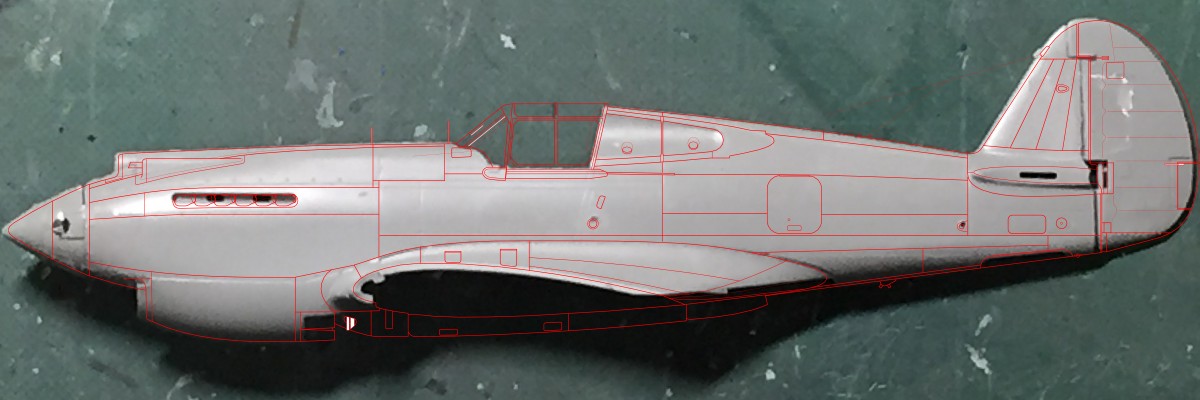
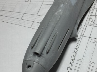
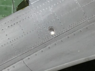
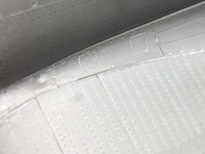
In addition, there are a few mistakes in the panel line. Although it is hard to see in the drawing, the shape of the slit through which the exhaust pipe of the cowl is incorrect. The slit of the kit is a horizontal straight line looking from right beside, but the actual aircraft is a straight line looking from diagonally above, therefore, if it is looked from right beside, the front end slightly droops down. This is a small thing, but it has a big influence on the impression of the appearance of the nose. |
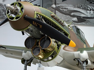 The radiator cowl is shaped to minimize the gap between the three drums. |
 The cowl cross section shape after D model (excluding F/L) is basically the same as B/C, because the three drums are the same shape. I think the cowl flap is common as well. (The image is inverted) |
|
|
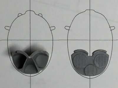
 The photo of the kit and my drawing are overlapped. The perspective error of the base photo is corrected with image software called "GIMP".
|
|
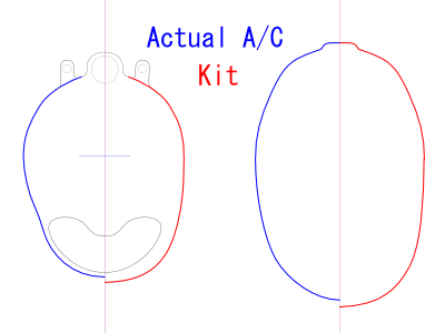
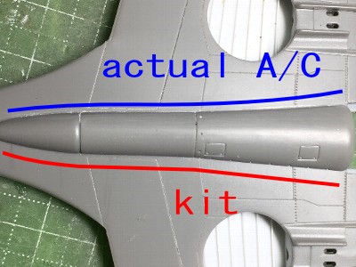
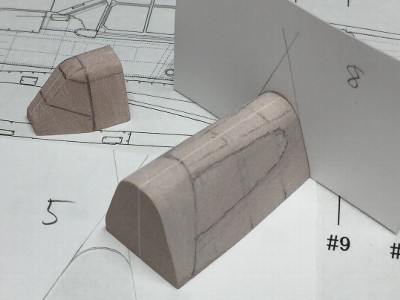
Next cross section shape. The radiator is not "U" but close to "V". In other words, the kit is a neck of Gibson Les Paul, the actual aircraft is Fender Stratocaster. Furthermore, the "constriction" at the upper end of the radiator intake is insufficient. Otherwise, the cross section shape and width of the rear fuselage is good. The shape and airfoil of the wing and fin are good as well. |
 Attention to the cross section shape of the jaw with the tape strip, and also, note the constriction of the intake. The "U" shaped cross section is that of Marlin Hawk P-40F/L. |
 Compared with the cross section, the difference is like this. However red line is an image. |
 Since the radiator part of the kit are not in the correct cross sectional shape, it also needs to be corrected. |
 The cross-sectional shape of the firewall is good. The width of the lower end is slightly excessive. The #5 frame behind the cockpit is good as well (no image). |
|
|
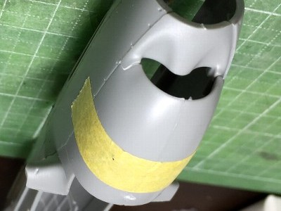
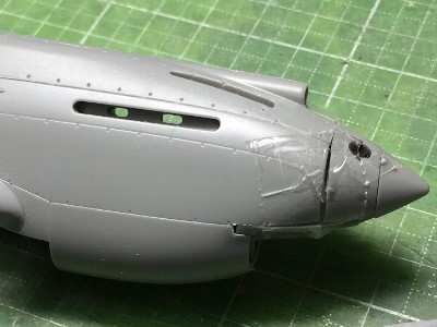
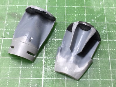
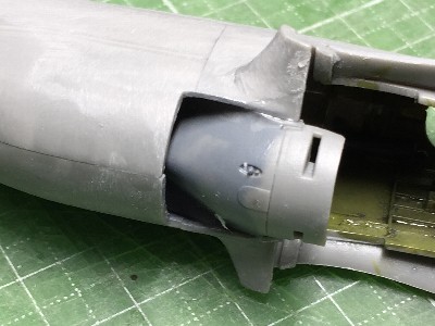
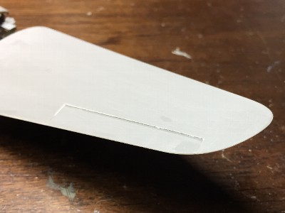
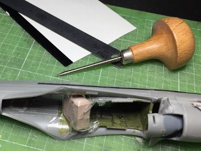
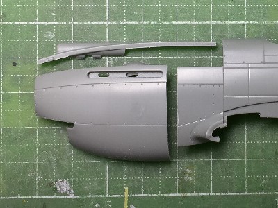 In order to shorten the nose length, the kit part was cut verticaly at the back of the exhaust pipe, and the cuting line was cut off by 1mm (.04"). The upper cowl is shortened by 1mm at the rear end. |
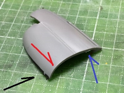 The parts were bent by hand. The red arrow was the direction to extend (decrease) the curve, and the blue was the direction to bend (increase) the curve. The black portion at the lower end (gluing line) was cut to shorten the outer circumference of the cowl and reduce its volume. |
 The chopped cowl was glued again. As the cross sectional area of the jaw decreases, the circumferential length decreases. Therefore, the lower end of the jaw part was cut. The leading edge of the intake lip was cut off by 1mm (.04"). |
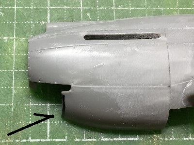
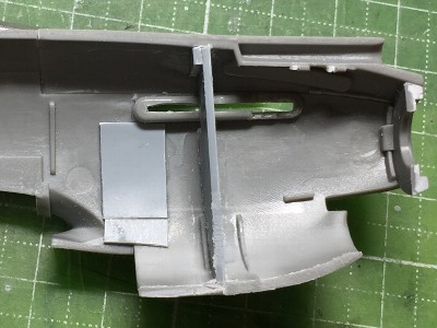 The bulkhead was inserted to prevent the bent cowl parts from returning to its initial shape. 1mm plastic sheet was cut out as my cross section drawing and its circumference was trimmed by 1mm. |
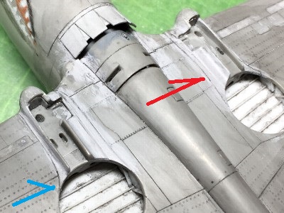
 This photo shows "Before"S correction. |
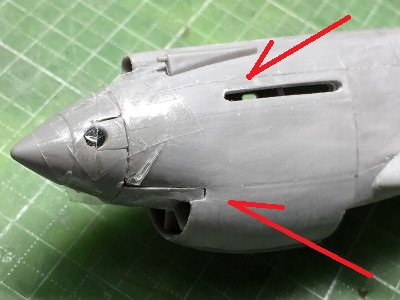 This is after correction. Note the constriction at the intake (the lower red arrow). The "ridge" in front of the intake connecting to the lip upper end also should be corrected. The ridge was moved to inside along with the constriction. The exhaust slit was also corrected (the upper red arrow). |
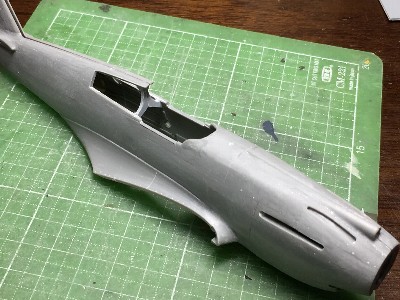
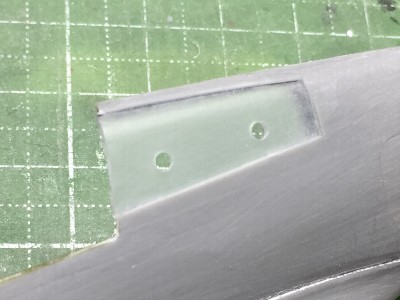
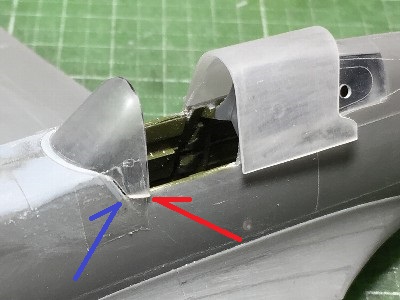
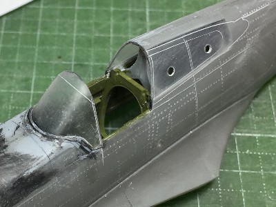
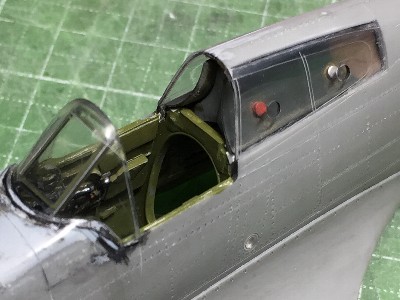
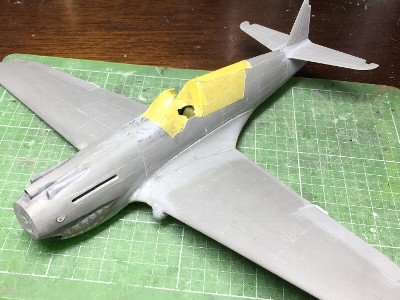
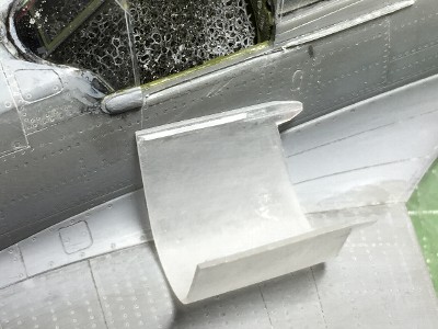
 The gluing surface of the rear fixed canopy of the kit can be seen from the outside. In order to replace the rear canopy with heat formed clear styrene, the fuselage was cut like this photo. |
 The fuselage panel inside the canopy would be fixed after the rear canopy glued. The navigation light was made of clear sprue and the diameter of the transparent part is enlarged. |
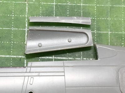
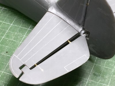
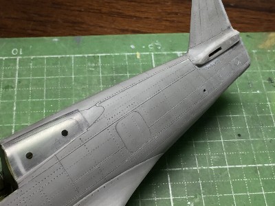
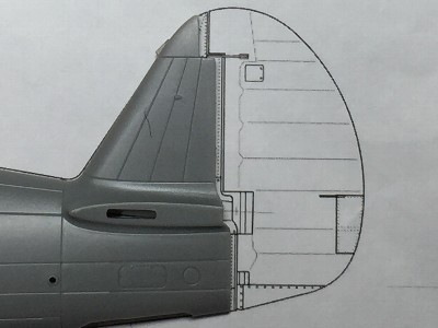 The fin is shorter by 1mm as this photo. |
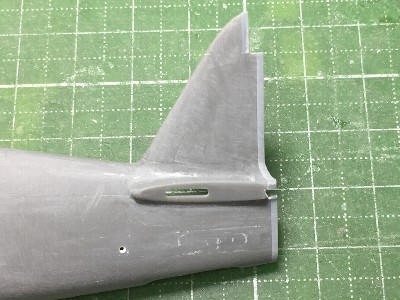 1mm plastic sheet was glued on the rear end. |
|
By the way, is it only me that the nose without the spina looks like capybara?
In this case, first, the right and left bulkhead of the nose and their positioning guide which holded each other were assembled. Next, the three parts of the cowl were glued to this bulkhead. Errors at this time were absorbed at the gluing point between the bulkhead and the cowl inside. Subsequently, the starboard cowl was assembled like the port cowl. This starboard cowl was temporarily fixed to the port cowl by the positioning guide, and in this state, the starboard rear fuselage was glued to the cowl with attention to the overall distortion. If I manage not to appear steps or gaps in all of the individual gluing portions, overall distortion occurs. It maybe the same with other things such as business or human relations. |
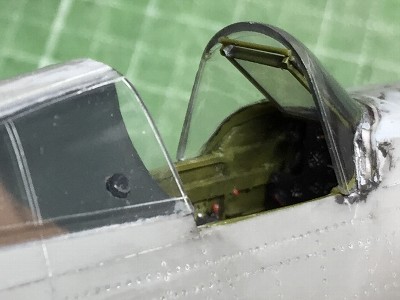
 Assemble of the starboard fuselage was finished. The upper part of the rear canopy that had been cut out was glued to the fuselage with the inner stay. |
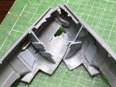 These are positioning guides and left and right bulkhead. |
|
|
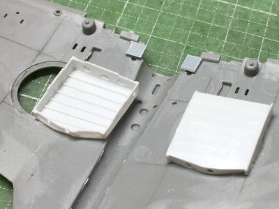
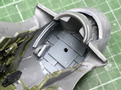
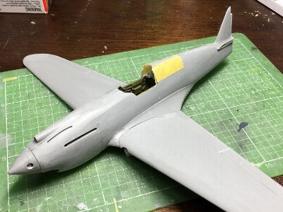
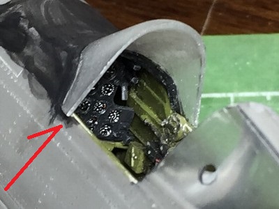
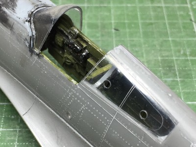
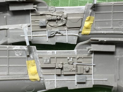 The brownish gray portions are from Aires resin set. Ribs were made of plastic strip (white). Additional equipments were from the kit and Hasegawa P-40. The throttle column was scratchbuilt. |
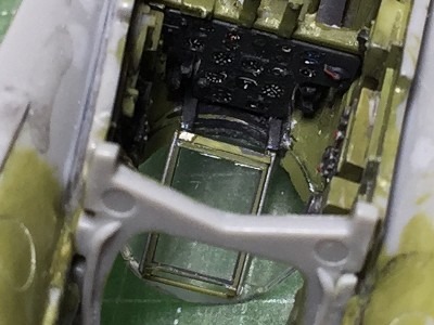
 The floor and frames of the kit were temporarily attached. You can see how Aires' side wall is compressed with comparing the stringers of the Aires and kit. |
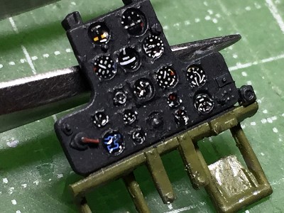
 The kit instrument panel was good for its molding. Aluminum sheet was attached behind the navigation light. |
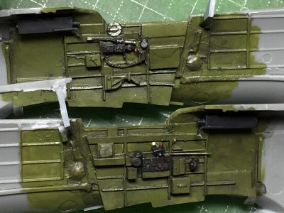 The cockpit was painted. I noticed after the completion that the cockpit of actual H81 and P-40B/C were painted in somewhat more yellowish color than interior green of my model. |
|
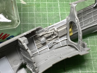
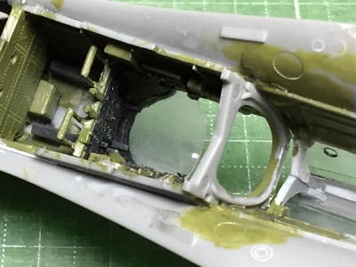
The upper edge of the kit cockpit was so thick that if the resin side wall was glued, the thickness of the edge became more than 2mm (.08"). Therefore, the edge of the kit was thinly sanded off (however, considering the rivet work afterwards, a certain level of thickness was left), a section at the top of the resin part was cut off. The knob of throttle lever was made in the way described below. CA glue was put on the top end of extended sprue or brass rod and it was put into plastic powder. This method is the easiest.
|
 Details were made of 0.3mm (.01") plastic sheet. They were glued with thin cement, and were cut and sanded after the next day. |
 Detail of the side wall of -B/C model. So, I referred to the E model. Unfortunately, I mistook the number of ribs. |
 The wing was reinforced solidly with carbon fiber. |
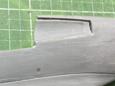
 The shape of the lower fairing was corrected with art knife. |
|
|
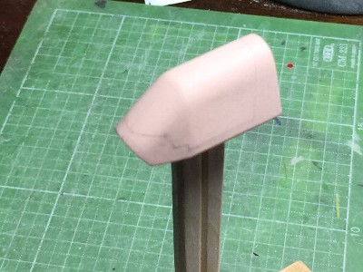
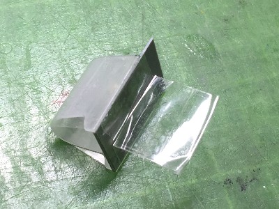
 The wood mold was almost finished. Pencil lines of the windows helped to notice a mistake of shape. The other wood mold behind this was for 1/72 Ju87. |
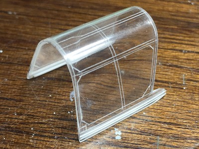
 The canopy was made of 0.4mm (.016") clear styrene (Tamiya Plaban). The final thickness became about 0.8mm (.03") because clear styrene sheet became thick when it was heated. |
|
Heat formed clear styrene sheet was cut out, and the inner surface was sanded off with #800 paper and polished. After gluing on the fuselage, the outer surface was sanded. I noticed the cross section of the fuel hole was a little thick. But, I had to endure, because if I made it thinner more than this, there was a possibility of occurrence of cracks. |
 The fuel hole on the port window was a surprising trap. The first trial part was a failure with cracks around the hole. This photo shows the second trial. |
|
|
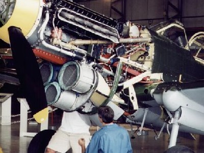
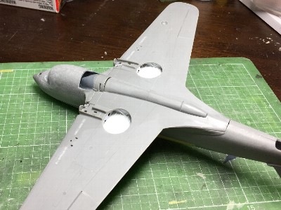
 The radiator, oil cooler and their fairings were from the kit. The cross section shape was adjusted. |
 The position of radiator rear fairing was carefully adjusted. The width of the opening was adjusted as well. The shape of the wing fillet was corrected with CA glue and powder. |
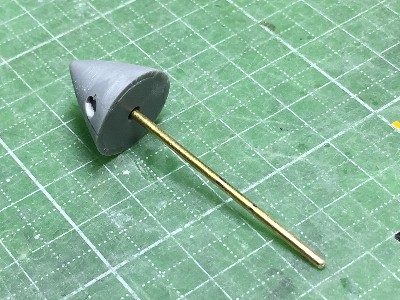 The spinner parts were glued and 1.5mm (.06") brass rod was glued. The kit sleeve part was glued on the front of the fuselage because there was 1.5mm hole already. |
 The rear sleeve was plastic sheet with 1.5mm hole. This sleeve was glue with liquid cement and the position was carefully adjusted. |
|
|
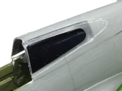
 The location of the kit landing light was not accurate. The position was removed to the correct position. The glass of the light was made of clear plastic plate of a DVD case. The reflector was made of alminum sheet. |
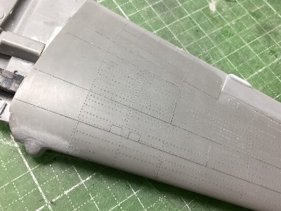
 The trailing edge of the kit was so much thick. It was sanded with #180 sand paper pasted on a ruler. The wing tip was sanded to be thin as well. The wing tip edges of most of actual aircraft are sharp, but most of plastic model are dull. I think this work is very important for the quarity of completed model. |
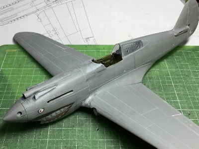
 The wing was temporary assembled with the fuselage and fitting was confirmed. |
 This is the lower side. The dent of ammunition box was filled with CA glue and powder. Can you see gray sprue in holes for reinforcement? |
|
|
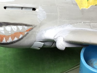
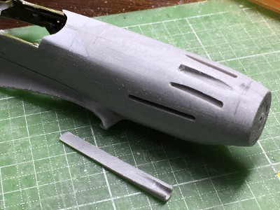 The upper intake was deleted. Then the upper nose outline shape was corrected with adding plastic sheet and sanding. The edge line was checked by the shadow line. The fuselage was rolled slowly under the desk light. |
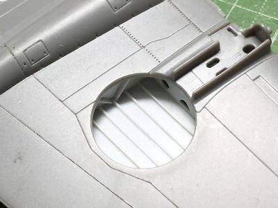
 The intake was from kit sprue. The kit gun fairing was too thin and too close to the center. |
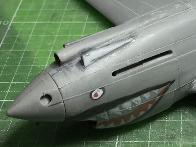 So 0.3mm (.01") plastic sheet (white) was glued on the outside. Shark mouth and eye were temporary painted to check the nose outline image. |
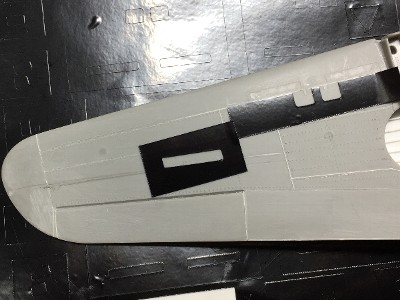
 The black template for engraving of the rear window was cut with cutting machine. |
|
Concurrently, panel lines were engraved. In this case, I used GIS Creos Line Chisel 0.1mm mainly. It tends to not go straight but bend sideways. So, first, I used needle or photo etching saw with template, then I change to line chisel for finishing work. Also, Mr. Line Chisel doesn't like putty and CA glue. So I don't use him on such surface but use a etching saw. |
 The whole shape appeared. |
|
|
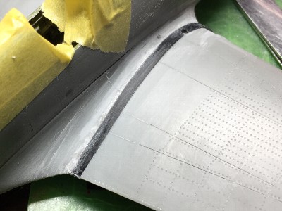
 The stab would be removed rearward a little by this photo. The gap between the fillet was filled with CA glue and powder. The elevator was joined with brass rod. |
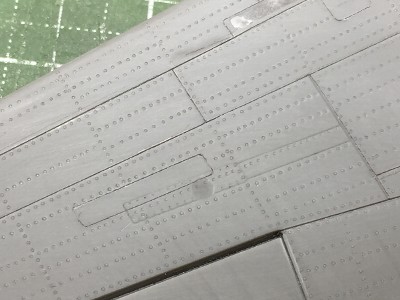
 The #1 beading tool was used for rivet engraving. A few rivet lines were omitted because they overcrowded. |
 The wing panel lines were engraved. Access panels were done with machine cut template. |
 The wing riveting was started. Please refer my drawings for correct rivet lines. |
|
|
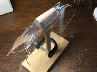
 The wood mold was made of chemical wood. The shape was simple. BUT, paradoxically, it was so defficult to fit the kit fuselage because the shape was simple. |
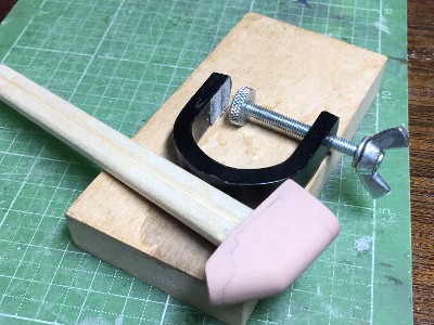 When I did heat forming, I uses such device. The wood mold was glued on a 4" wood rod (you know this is chopstic). And the rod was clamped on the small wood bench. |
|
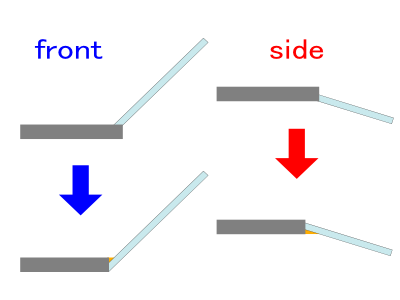
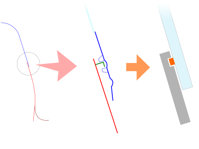
The cross section of the wind screen was changed as following picture. The gluing surface of kit clear parts were visible from outside. So I chanded to hide gluing surface from outside. The left figures shows its side vies and the right shows top view. The small orange portion means they were filled with putty or CA glue. |
 |
|
|
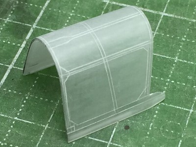
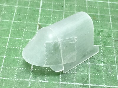 The shape and size of the wood mold was adjusted several times. 0.4mm (.015") clear styrene was heat formed, cut out, sanded roughly and then cut by etching saw. |
 Fitting for the fuselage was adjusted. The height, angle of front window and horizontal position were strictly checked with template which was a cut out of my drawings. |
|
The relationship of wind screen and fuselage of P-40B/C was unique. There is no step at the blue arrow point in above picture. But, there is a step at the red arrow. Because the slide hool is overlapped on the fuselage. The step will be hided with the fairing.
|
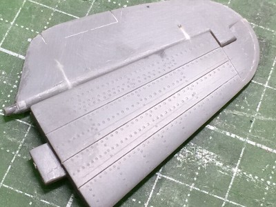
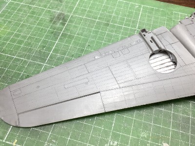
 Riveting of the wing was almost finished. The number of stringer was so many but I managed to depict as my drawings. |
 |
 These are riveting tools. Cutting sheet was used for guides. Two sheet was stacked and then cut. A wood block was inserted for reinforcement. |
 Main rivets were done with #1 beading tool and fasteners of wing fillet were #3. |
|
|
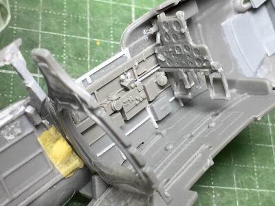
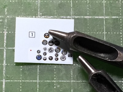 The instrument panel was going to be finished. Kit decals were punched out individualy. |
 Each decal was applied and Future was put on each meter. Some meters were tone downed with dark gray paint drybrush. |
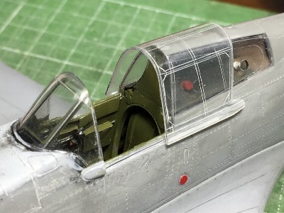
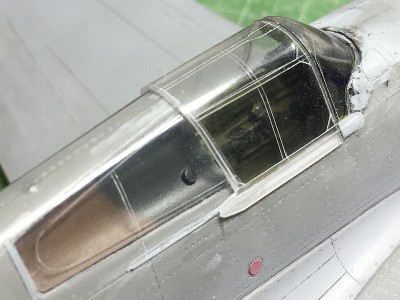
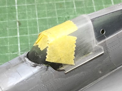 The wind screen was glued on the fuselage. It was not glued in stand alone but was temporary fixed to the slide hood and glued with liquid cement. By this method, the positional relationship between the wind screen and slide hood becomes appropriate at completion. |
 The gap between the wind screen and the fuselage was filled with CA glue and powder. It was painted in black to check its finish. Note the lower end of the frame protrude from the fuselage (red arrow). |
 The instrument panel was glued from the lower opening. The base of bullet proof glass was made of plastic strip and glued on the top of the instrument panel. |
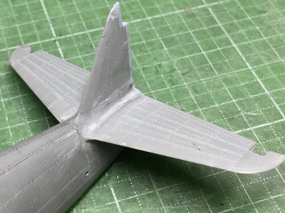 The stabilizer was glued. |
 Frames were engraved. Some frames were engraved with a hand made 0.3mm (.01") double needle. |
 The outer surface was polished with rubbing compound using a hand router and cotton swab. The inner surface of the rear window was polished as well. That why the inner panel was removed. |
 The bullet proof glass was made of DVD case. It was masked with Scotch tape. |
 I intended to insert the inner panel like this. But..... |
 It could not be inserted. So it was broken down. The fuel cap was put on. Then they were painted, polished with Raplos and weathering washed. |
 Details of connecting rod and mount were added on the bullet proof. Then they were glued in the cockpit with liquid cement. |
 The clear styrene of the wind screen was thicker than actual aircraft in scale. So the assemble was not strictly accurate. |
 The lower edge of the bullet proof glass was glued on small strips. |
|
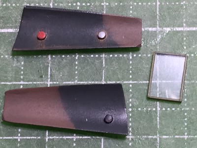
The bullet proof glass of the actual aircraft was set with right side down a little to avoid a duplicate of gun sight reflection. But this inclination was not depicted. The small square glass of gun sight reflector was omitted as well. Well it was impossible. The positioning of bullet proof glass was so difficult that it would be impossible after the wing was glued. The cross section of the rear fuel hole was painted in dark gray to hide the thickness.
|
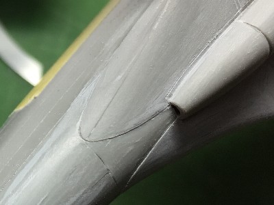
 The bulge of landeng gear base and the aileron tab was glued. |
 The navigation light and landing light were engraved and polished. |
 Then the wing was glued. The canopy was protected with Tamiya tape. |
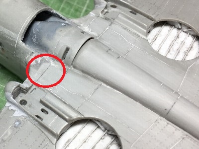 The kit wing dented at the red circle. The joint portions of wing and fillet were bent to outer (lower) direction. Then the dented portion was Sraised up. |
|
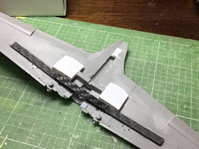
The cowl flap was scratchbuilt with plastic sheet. The planer shape of the kit gear fairing was incorrect. |
 Two plies of 0.5mm (.02") plastic sheet were bent and glued together, then they were temporary put on a rod. Then individual flaps were glued on them. |
 The finished flap was glued behind the cowl. The shape of the gear fairing was corrected. 0.14mm (.005") plastic sheet was glued (red arrow) and the panel line was re-engraved (blue arrow). |
 The wing fillet and gear bulge were finished with CA glue and powder. |
 To make a small step between the wing and fillet, cutting sheet (black) was pasted and CA glue and powder were put on the fillet. |
 The step on the lower side of the fillet was depicted with a chisel and knife. |
 Rivets of the upper wing near the fillet were not engraved until the wing was glued. Then they were engraved. The fastener of the fillet was #3 and engine cowl was #5 beading tool. |
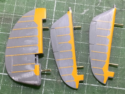 Rib tapes were depicted with custom made dry decals. They were ordered at the same time when I made P-51A. Some minor differences were fixed with surfacer. |
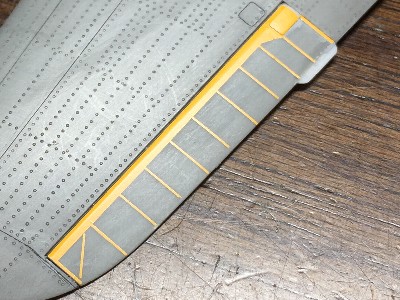 The aileron ribs were the same. The small access panel was 0.14mm (.005") plastic sheet. |
|
|
 |
|
The heat formed slide hood part was slightly loose-fitting. So, in order to narrow its width, the hood was fixed to the gauge made of plastic sheet with scotch tape, then the hood was dipped into boiling water several seconds. The rear half of the slide rail was made of 0.2mm (.008") plastic sheet. It was glued into a engraved line. |
 The top portion only was dipped into boiling water. |
 The inside rail was made of 0.3mm plastic sheet (white). |
 Frames were engraved with double needle. It was a tough work that the line was engraved in the center of 0.6mm (.024") width double lines. The center frame was 0.4mm (.016") width. |
The final thickness of the hood became 0.5mm (.02"). It was polished with extreme care not to make a crack. It was not completely polished, but I could not go any more, because I was scared. |
 This is the close position. |
 Finally, two thin line of extended sprue were glue on the lower frame. It was very difficult to glue two lines in parallel and horizontal. |
|