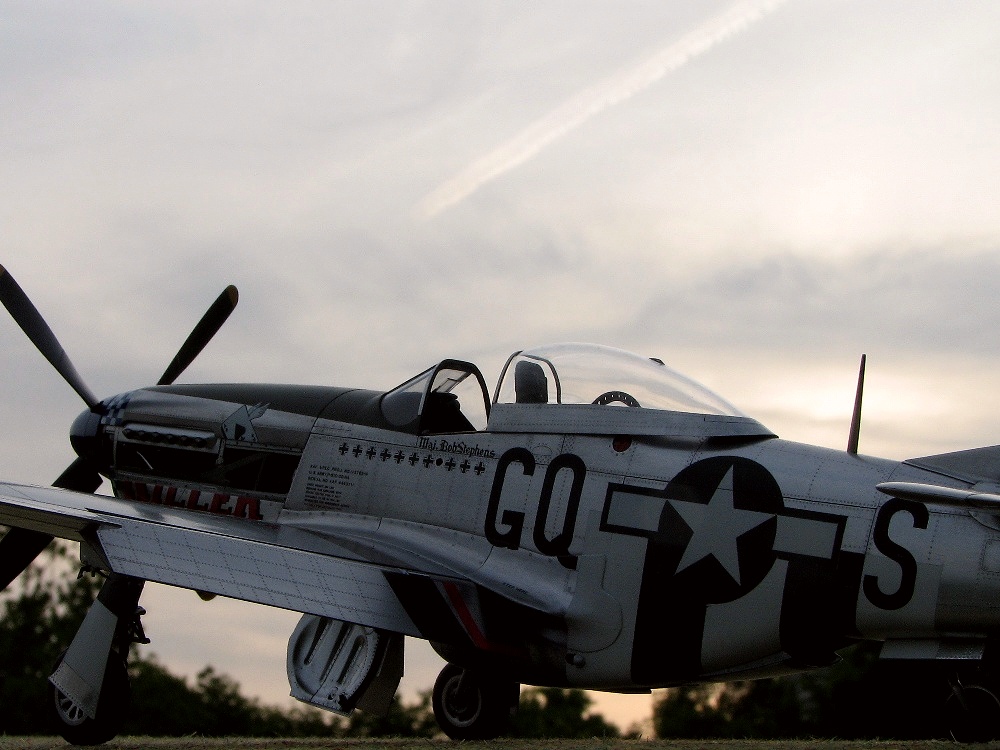
P-51D Mustang Tamiya 1/32 part-1
5/2013
|
|
Great thanks to Larry for English text!!
|
|
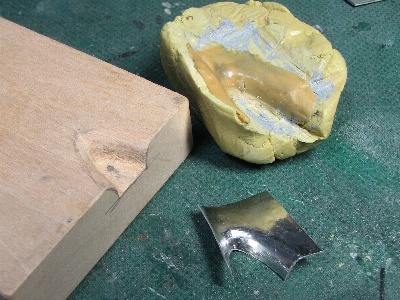
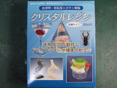 I used this transparent resin. |
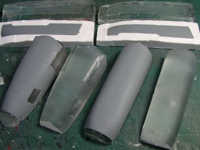 Platforms are cast using silicon molds. White objects are portions of the silicon molds. |
|
|
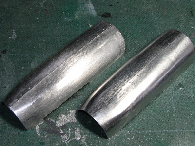
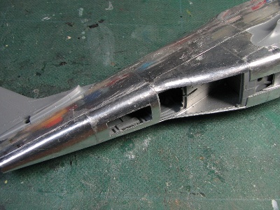
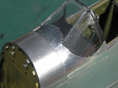
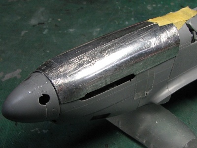 The upper cowl is covered with two panels. The shape is checked on the kit part. |
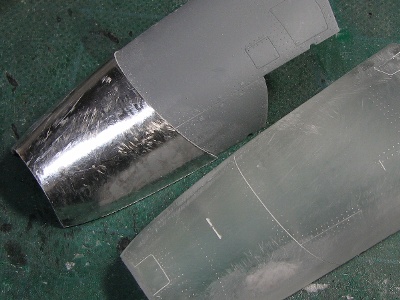 The lower panel is formed. |
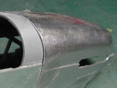
 The port side panel of upper cowl is glued. |
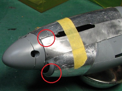 But glued position is not accurate. Gaps became visible (red circles). |
|
I had to make another try. I ordered one more set of cowling parts from Tamiya after service. |
 The small piece of plastic sheet is temporarily glued as a guide. The kit part is set on the resin platform. Kitchen wrapping sheet is laid between the kit part and the resin, so they are not glued together. |
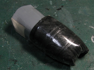 Aluminum sheet is pressed with urethane foam and scotch tape while gluing. The reason why the resin platform is needed. |
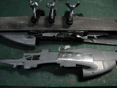 In parallel, the fuselage panel was glued. The part is clamped while gluing. Small holes are drilled in plastic part surface to let excess epoxy glue escape (see the port fuselage). |
 The fuselage, in process. |
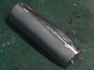
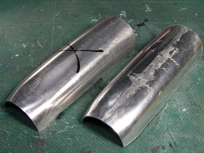
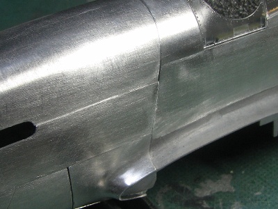
 This is the second try. There are no gaps, unfortunately though, a step shows at the rear of the panel. Oops, I have to make a third try. |
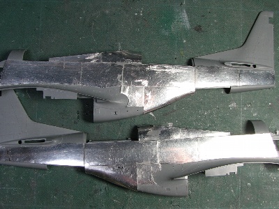
 The left is the second try, the right is the third try. |
 This is the third try, There still remains a small step, but it may be insignificant |
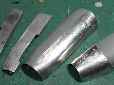
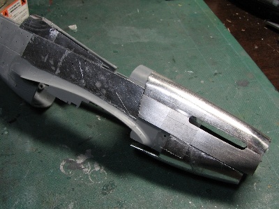
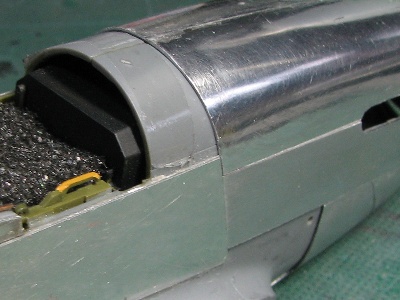
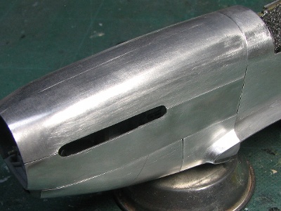
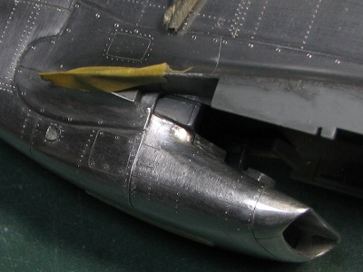
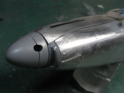 The lower cowl is in process. The intake lip and spinner shall not be covered with aluminum. |
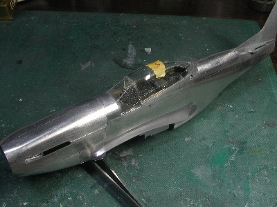
 Almost finished, in this view, left and right fuselage parts can be glued together. |
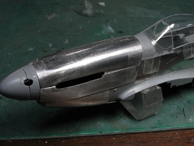 The contingence of cowl panels is checked. Panels have not yet been trimmed. |
|
|
| B/C early ? | B/C late ? | D/K early | D/K late | |
| frames of cowl panel | NMF | NMF | NMF(*) | ZCY |
| oil tank | ZCY | NMF ? | ZCY | NMF |
| intake duct | NMF ? | NMF ? | NMF | ZCY |
| engine mount | ZCY | IG/BG | IG/BG | IG/BG |
| fire wall | IG/BG | ? | ZCY | IG/BG |
| inside of panels | NMF ? | NMF ? | NMF | ZCY ? |
|
|
|
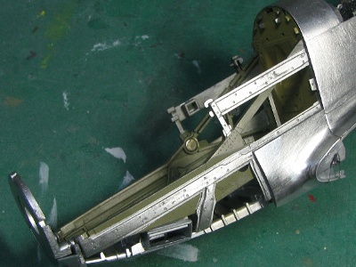
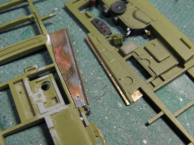 The slide rail is added inside of the frame. |
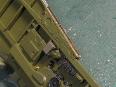 The rail is made of brass sheet and fine brass rod. |
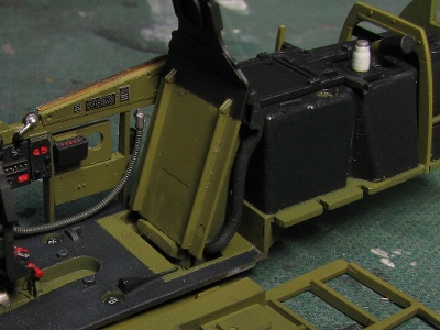 The black portion of the bullet proof plate is altered from the kit instruction. The white cylinder is a transparent bottle on the actual aircraft. |
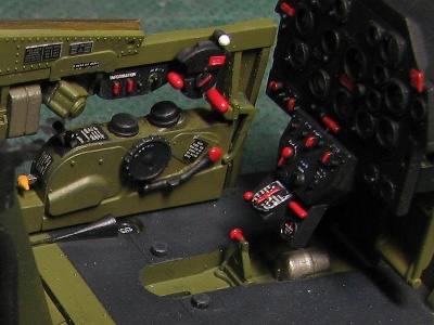 Caution letters are painted with fine brush. Some letters are decals. The circle on the floor is fuel gauge. |
|
The antenna wire P-51Ds of 8th AF operated from the base in GB did not equip antenna wire from the canopy to the tail fin. The reason was that SCR-522 radio system did not need antenna wire, they used blade antenna. On the other hand, P-51Ds in Italy, Asia, and Korea were equipped with an antenna wire.
|
 |
 |
|
|
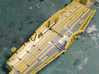
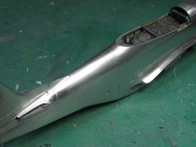
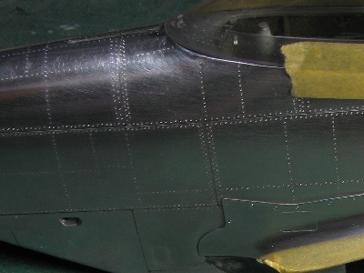
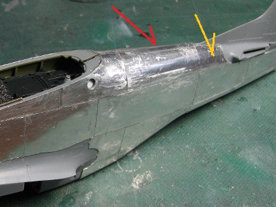 The top panel (red arrow) is worked after the fuselage glued. The yellow panel is glued after the top panel. |
 The lower side is finished. |
|
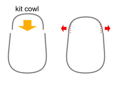
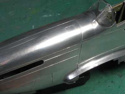
The third try of the upper cowl panel did not turn out as accurate as I'd hoped. The face angle of the upper cowl and side cowl did not conform well together. The reason is; the kit upper cowl parts are designed slightly tight to hold to the fuselage with its elastic force. My resin platform was accurately cast to the Tamiya cowl, so aluminum sheet was formed and glued to the Tamiya cowl shape. Well, I took that challenge and made a fourth attempt. For this try the resin platform was corrected with putty and a corrected cowl was generated. |
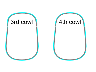
 The left is third and the right is forth. The difference is not visible in this photo. |
 But looking at this photo, the forth cowl is checked and it's OK. |
 |
 |
|
|
 Here is the constructed female die. The results are accurate. |
 |
|
|
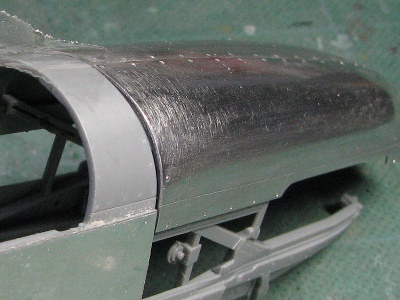
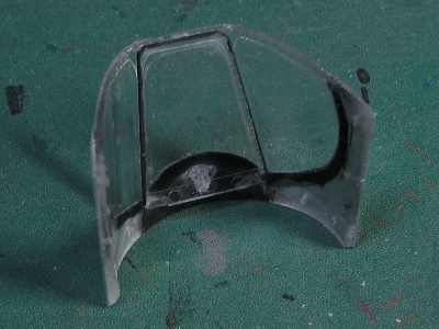
 The ceiling is painted with Mr. Super Fine Silver. |
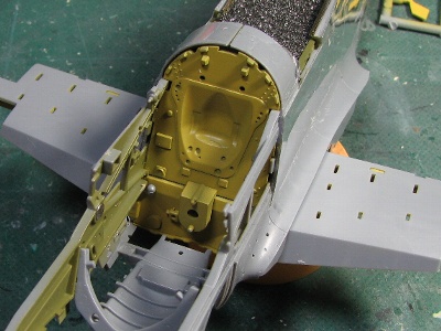 The firewall is Zinc Chromate Yellow. |
|
|
 The surface is polished with #600 grit sand paper. |
 Trimming of the panel edge is not complete. |
 Small tabs are glued on the inner cowl edge. |
 Then, panel edges are trimmed. |
|
|
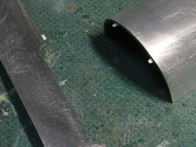
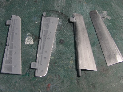
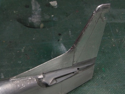 The tail fin and dorsal fin were 0.2mm (0.008") aluminum sheet. |
 The wing filet is 0.2mm sheet as well. |
 The inside of aluminum sheet is painted black. |
 These panels are 0.2mm sheet. |
|
|
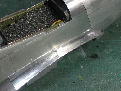
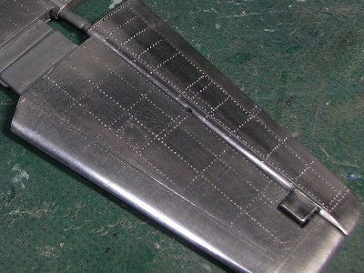
 The surface is polished. |
 The engine bay is painted. |
 Panel lines are engraved with a needle. |
 Rivets are engraved. |
|
|
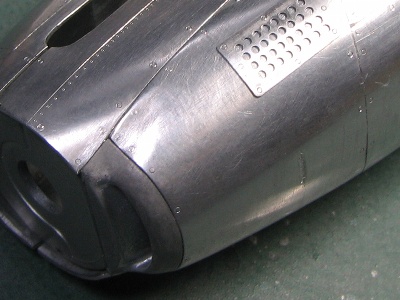
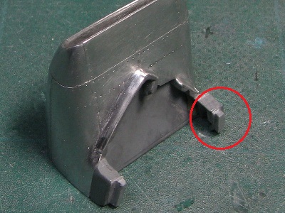 The small plastic tip is glued on the intake parts (red circle) to temporally fix the intake to the fuselage. |
 The intake part is not glued on the fuselage until the wing is glued. |
|
|
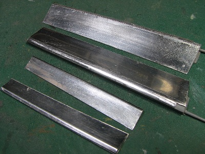
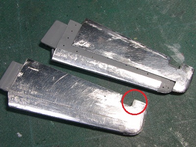 The horizontal fin was almost the same as the vertical fin. Tip panels were combined to the inside panels to delete thin panel portion at the red circle. |
 Aluminum sheets are glued separately, the joining portions are sanded very thin. Then the upper and lower parts are glued. |
 Polished and engraved. The kit control surface is movable but the hinge mechanism stands in the way of aluminum works. So I gave up the movable hinge animation. |
 Aluminum sheets are glued on the flap and aileron. They will remain fixed as well. |
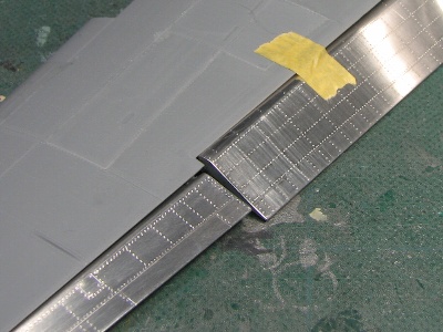 Panel lines and rivets are engraved. |
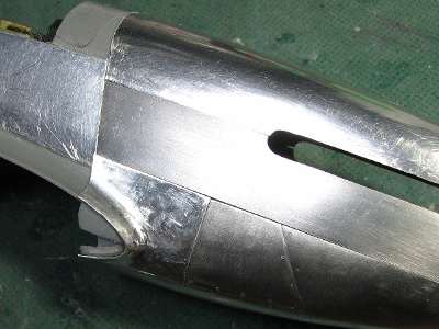
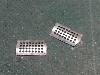 These holes are opened with a drill and a fine file. |
 The cowl panel behind the perforated panel will be cut out. |
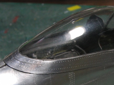 The canopy frame is finished. |
|
|
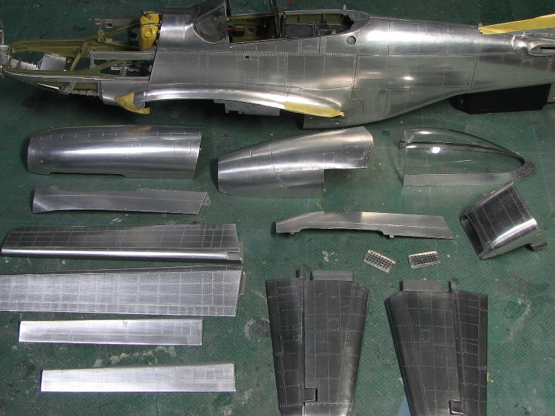 These are all of the main aluminum parts after six months of efforts. |
|
|