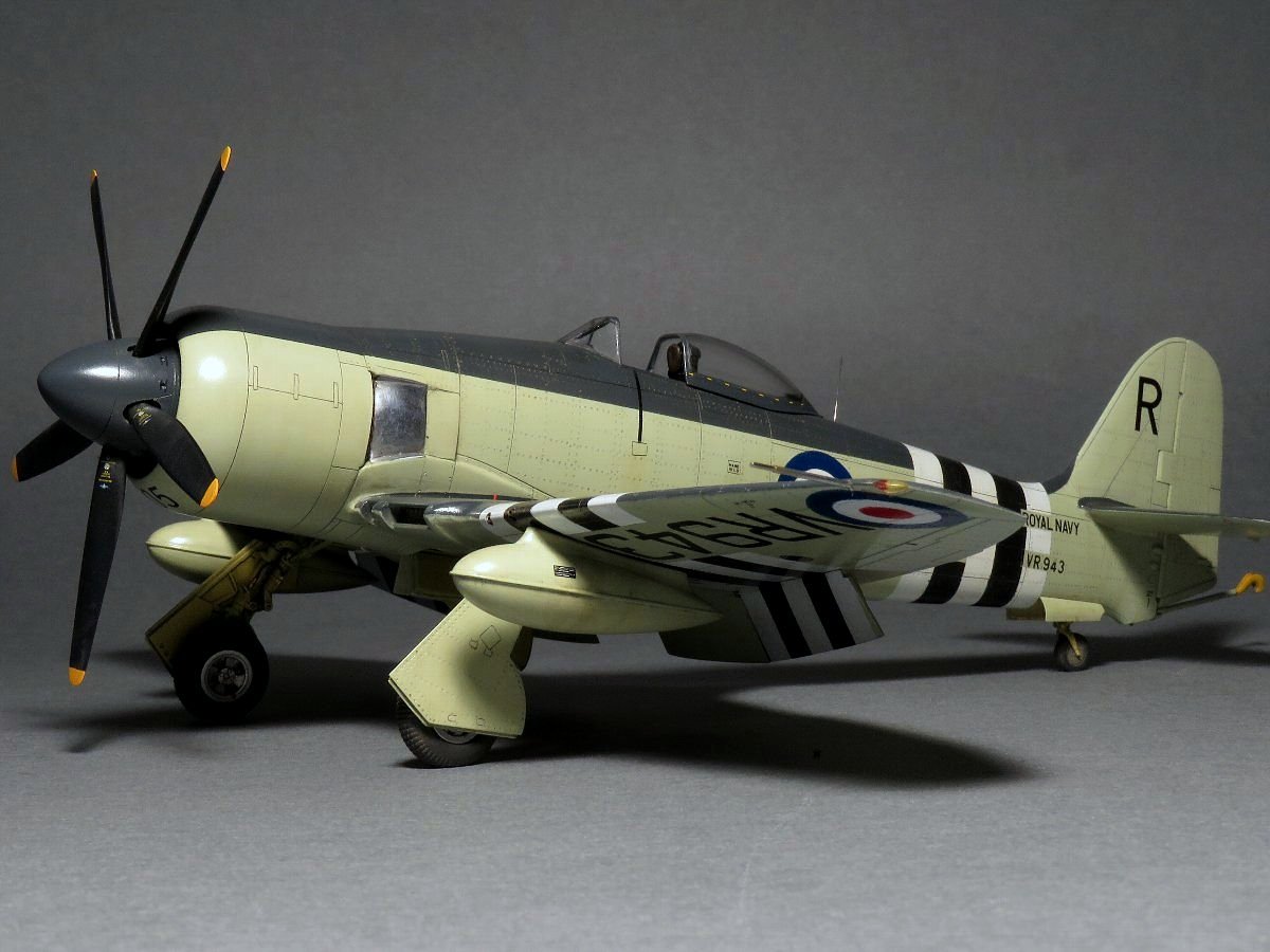
Hawker Sea Fury FB.11 Airfix 1/48 part-1
|
|
|
|
|
|

|
|
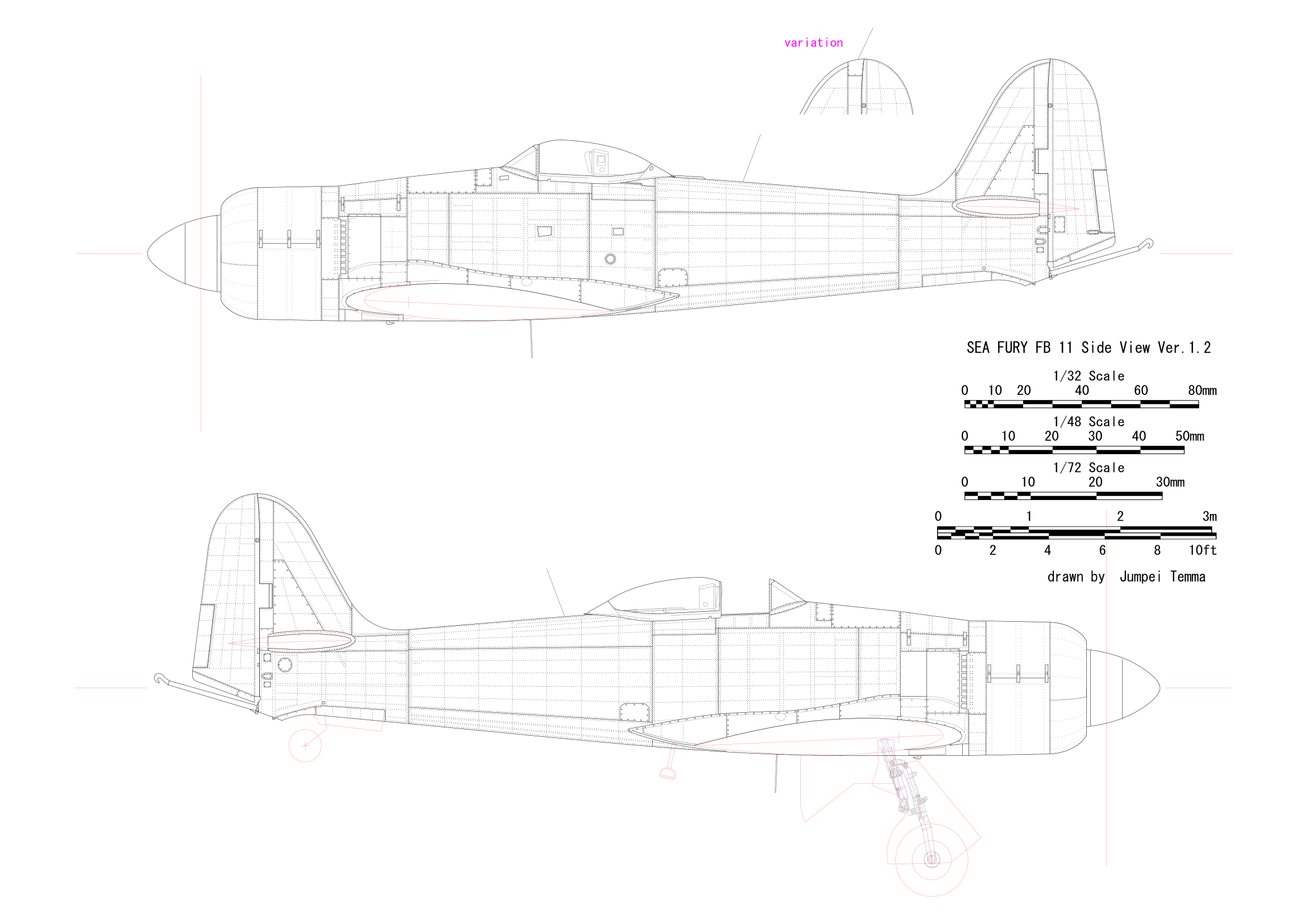
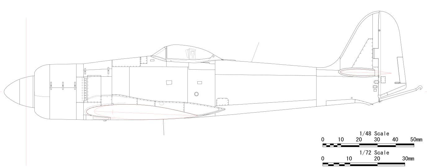
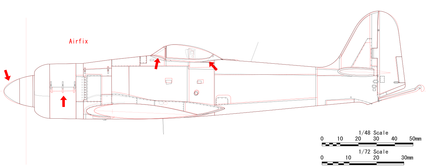
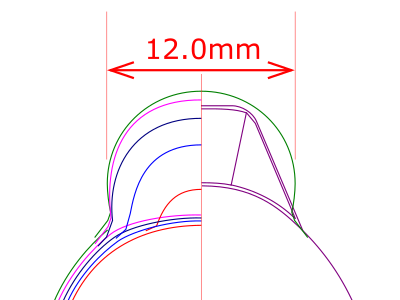
This is an enlarged cross-sectional view. The rear fuselage is not symmetrical in the vertical direction. This cross-sectional shape is different from that of Typhoon and Tempest. The cowling is not a perfect cylinder but the rear is slightly thicker. |

|
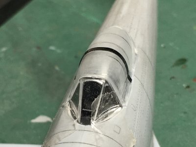
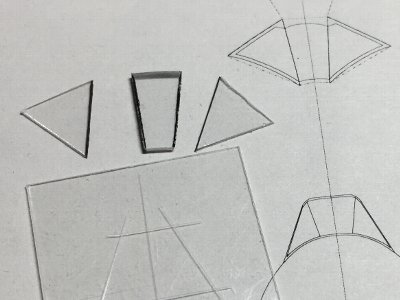
First of all, the windscreen is unique. It can only be seen on this aircraft. At first glance, it looks like an ordinary front window frame, but when looking closely, there is no front frame. And when looking better, a plate-like window frame is sandwiched between the front and side glasses. It's hard to explain in words so look at photos. |
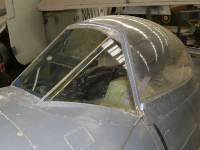 The portion that looks like the front window frame is the plate-like frame locating inside the windscreen looked through the side glass. The reflection of the light shows that it is not the frame but the glass. |
 This is the view of the window frame looking foreward. Be careful with the plate-like window frame on both sides of the front window. They become somewhat narrowing rearward, and the bulletproof glass with the side cut diagonally may be set there. |
|
The structure of this windscreen is the same as Typhoon (bubble top) and Tempest. Next is the slide hood. The shape of its lower frame is also characteristic. Compared to the Spitfire, the outline of the rear half is completely different. Although following all images are existing restored aircraft, the shape is the same as original aircraft. |
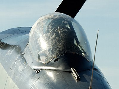
 The bubble shape cross section seems to be a perfect sphere when viewed from the front. The kit lacks this lateral swelling at all. |
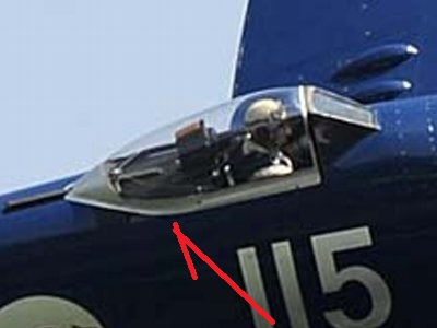 The lower frame is a straight line in parallel. It is bent at the red arrow, and the rear half is also a straight line. |
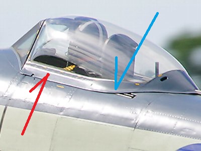 The folding of the frame is not simple, it is bent in the upper 1/3 in the first half (red). The second half is about lower 1/3 (blue). |
 Note the shape of the frame and the bubble-like swelling of the plexiglass, etc. |
|
|
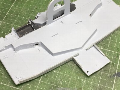
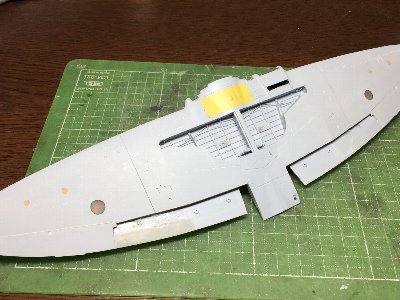
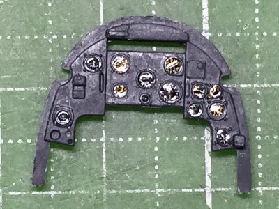 The instrument panel is from the kit. Kit decals are pasted. Future wax is painted. |
 Details of kit parts are rather poor. |
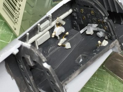 Frames are depicted with plastic strips. Instruments are from the kit or scratched. The foot bar is glued rearward. |
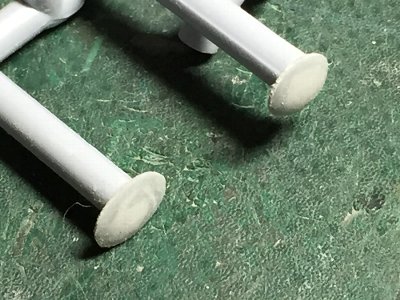
 Knobs are depicted with CA glue and plastic powder. CA glue is put on the tip of a brass rod. Then the rod is dipped into powder. Cables are depicted with 0.3mm lead wire. |
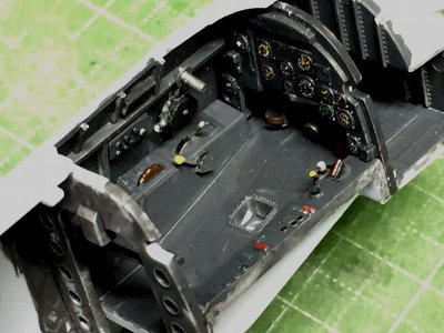 Coloring of knobs are fiction. The kit's control stick is located rearward the actual aircraft. But I do not correct. |
 The compass will be installed later. |
|
|
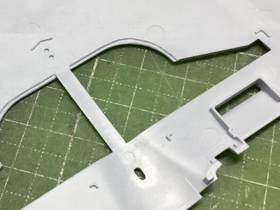
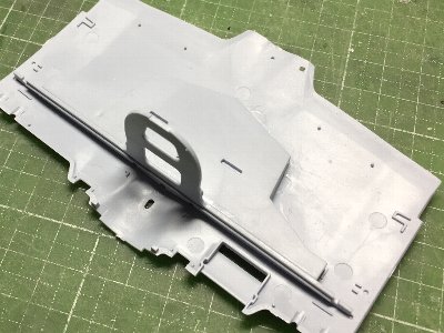
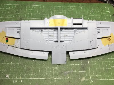
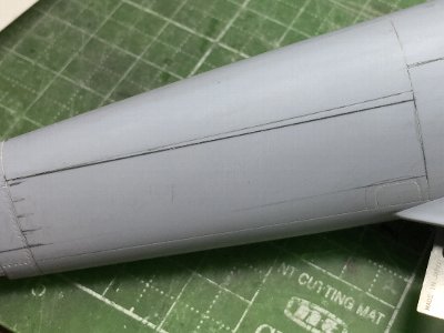
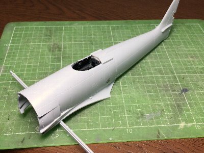 Fuselage parts are glued. The wing spar is temporary fitted. |
 The kit original starboard part is bent. |
 The trailing edge is cut off and plastic sheet is glued. |
 The small window is depicted with clear sprue. |
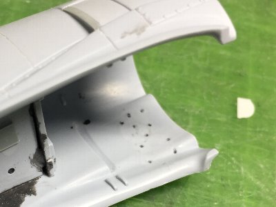
 Natural metal portion will be depicted with aluminum sheet. So the surface is scraped by about 0.3mm (0.01") with a chisel. |
 The kit center part of the cowl is a little small. So 0.5mm (.02") plastic sheet is inserted between the upper and lower parts. |
|
|
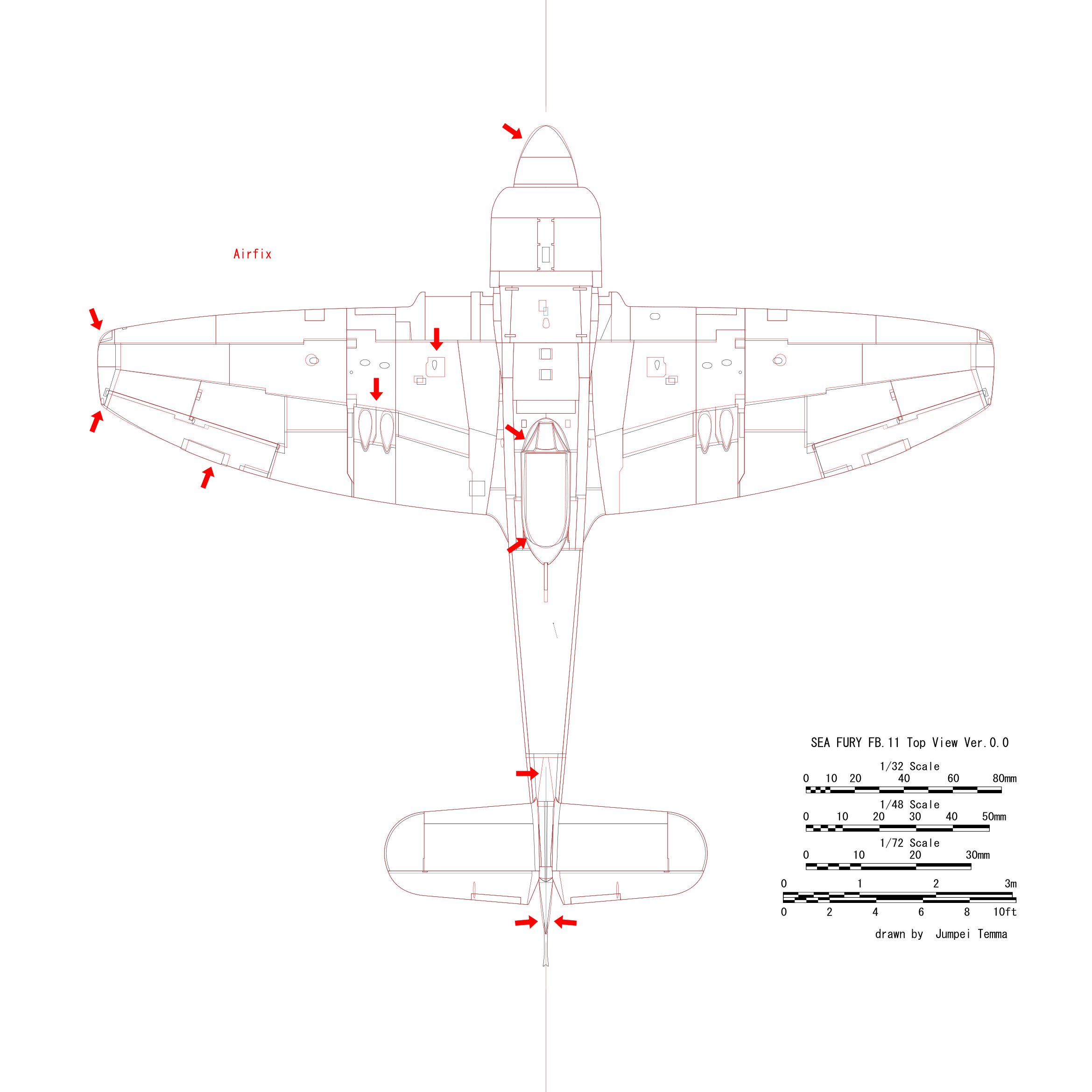
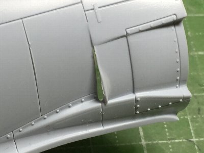
 This is the original starboard inner wing. |
 The blister portion is replaced with plastic material (the unnecessary gear cover part of the kit). The outer wing is glued and their surface is sanded to be flat. |
 The edge of the gear well is cut to be thin as step-like. |
 The front wall of the gear well integrated with the fire wall are glued first to the lower wing. |
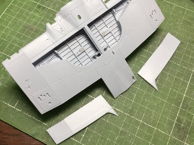 Flap portions are cut off. It is easier to cut the fillets together. Push pin marks of the gear well are filled with putty. |
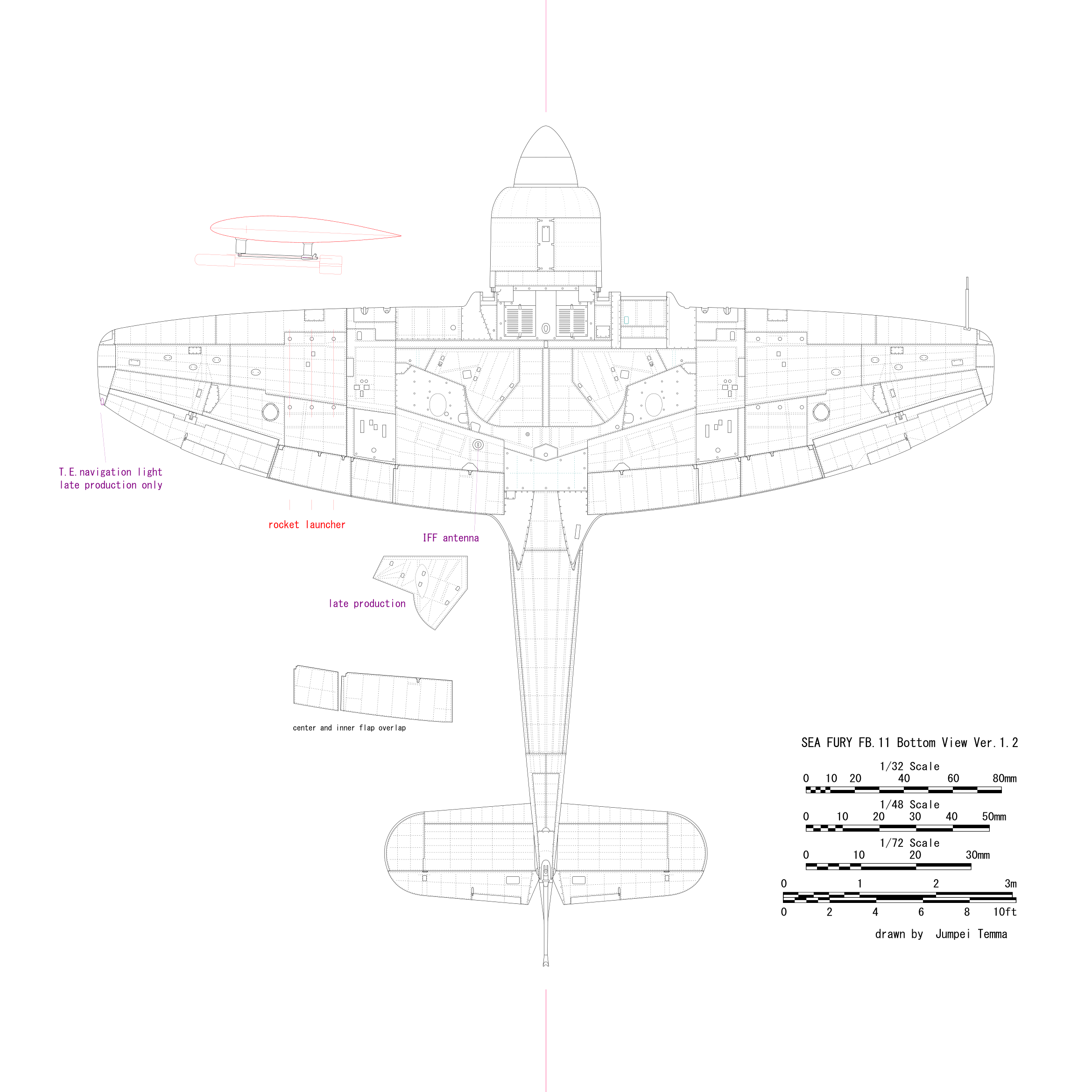
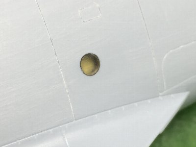
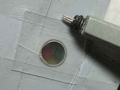
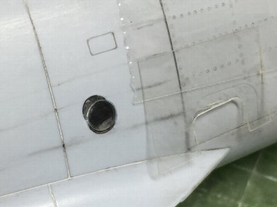
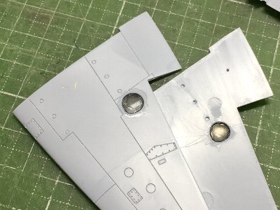 The navigation light window is replaced with the transparent plastic of the DVD case. |
|
|
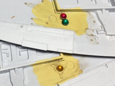 The port side is amber, the starboard side is red and blue. |
 Also the inside wall is set behind the window. |
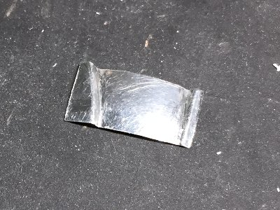 0.2mm (.008") aluminum sheet is cut and bent. There are broken line on the upper and lower portions, and the middle part is a strong convex surface. Therefore, it is difficult to bend correctly. |
 I always use epoxy glue for aluminum sheet, but this is only one time so I use CA glue. |
 Small holes are drilled in the plastic part and CA glue is filled from inside. |
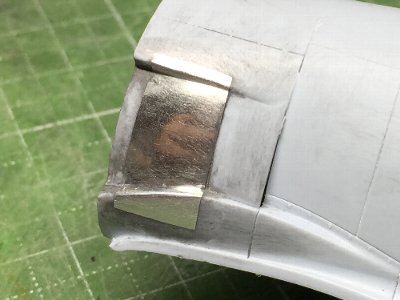 The surface is sanded and roughly polished. |
|
|
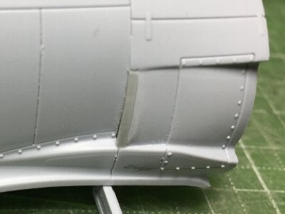
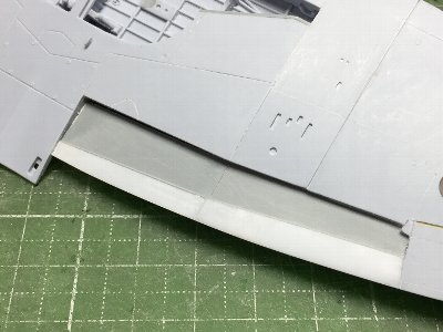
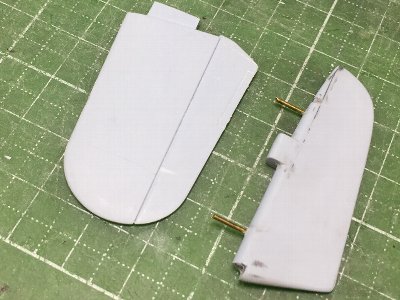
 A strip of 1mm (.04") thick plastic sheet is glued on the front end of the flap. The gear well part is glued. |
 At first, joined outer and inner upper wing part is glued on the inner lower wing. |
 Then the outer lower wing part is glued. Shores of sprue are glued (yellow). |
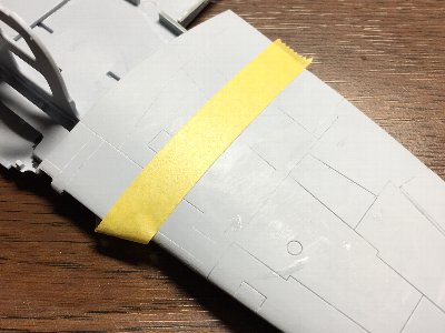 In order to keep the sharp break line, masking tape is pasted and then the surface is sanded. |
|
|
 Surfacer is filled in thick panel lines. |
 Plastic sheet is glued on the inside of the flap. |
 A template for the navigation light frame is made of plastic sheet. And the frame is engraved with a double needle. |
 The wing tip light is made of clear sprue. The cross sechiton is painted in Hawker Yellow. |
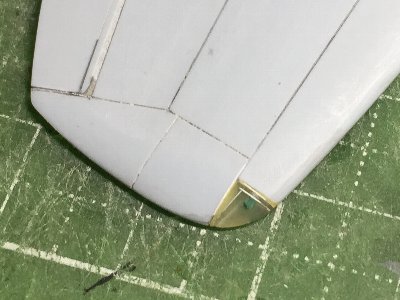
 The rudder and elevator are fixed with brass rods. The convex surface of the rudder is sanded to be flat. |
 The lower leading edge of the fin is sanded to be thin (pencil hatching). |
|
|
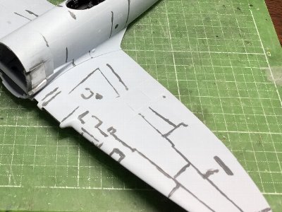
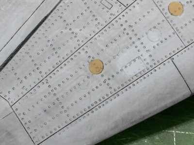 Rivets are engraved with beading tools. #1 needle (0.3mm) is mainly used. |
 Some panel lines on the fuselage are not match to rivet lines. So they are filled with CA glue and re-engraved. |
 The kit small window is not matched rivet lines as well. So the position is corrected. |
 90% of fuselage rivets are finished. |
|
|
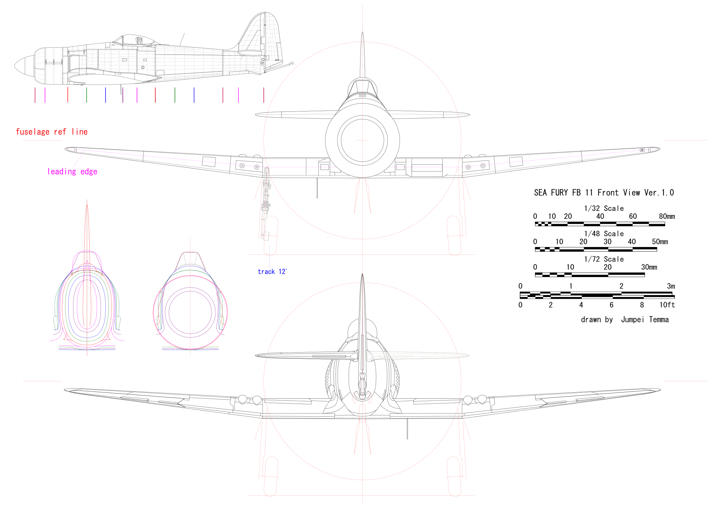
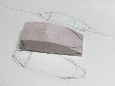 The wood mold is made of chemical wood. The side view and front view shapes are carved at first. Then corners are trimmed. |
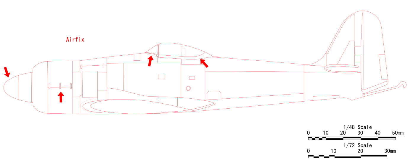
 The size and shape are checked with my drawings. The cross section shape is different from the kit part. |
 In order to check the shape, 0.5mm plastic sheet is heat formed. |
 Well, not so bad. |
 Cross section drawings of the canopy has been made. See its bubble shape and size. |
 The kit hood is not swelled. |
|
|
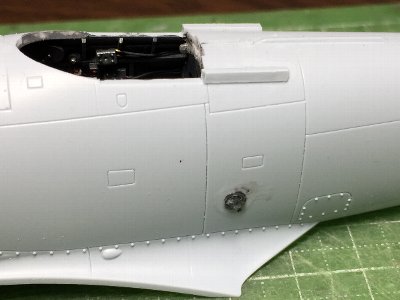
 There is a slight gap step between the wing and fuselage. |
 The wing surfaces is masked and fillets is sanded. |
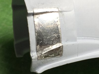
 A dent occurs in the aluminum part. Because CA glue was not filled properly on the back side. So that aluminum part is cut out and replaced with plastic sheet. |
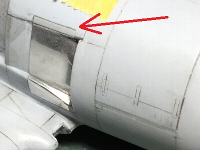
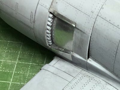
 The air filter inlet louver of the kit is incorrect. The kit is convex, but the actual aircraft is concave and the opening is on the front. But it is impossible to correct them by my hands. |
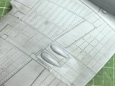
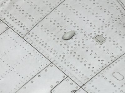
 Blisters are addee on the lower surface of the main wing fuel tank. 0.5mm plastic sheet is temporarily glued to the spruer for a handle. The center portion is filled with CA glue + plastic powder. |
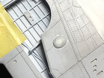 It is glued to the lower surface of the wing. |
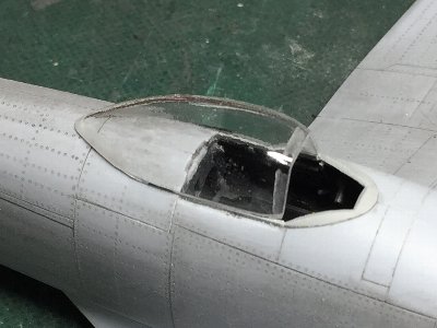
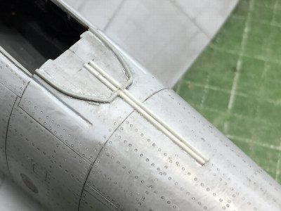
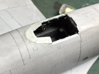 The windscreen base is added with 1.0mm plastic sheet. It is bent, glued and cut appropriately. |
 The opening is cut into the correct shape. The slide rail is also attached. |
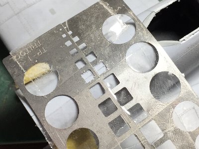 Fuel tank access panels are engraved. It is difficult to align the two squares. I failed to engrave them individually. They were filled with plastic sheet. This picture is Take 2. Two etching templates are fixed with Scotch tape. |
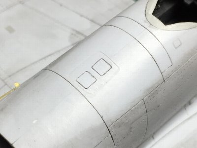 Finished. |
|
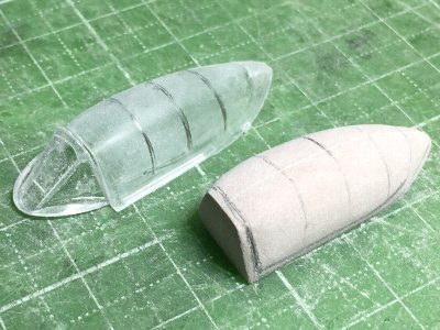
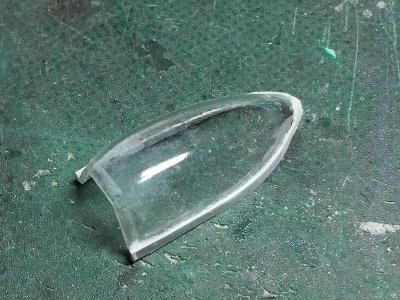
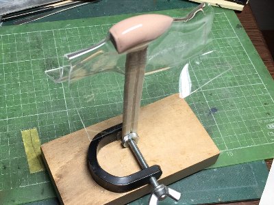
Although acrylic sheet is thick with āČ cross section, it can be removed from the mold somehow by trimming carefully. When it was cut out, shapeed, and set on the fuselage, I felt that the latter half shape was not insufficient. So I correct the mold and heat press again. |
 This is the Take 2 canopy. |
 0.5mm plastic sheet is glued with CA glue as the bottom frame. |
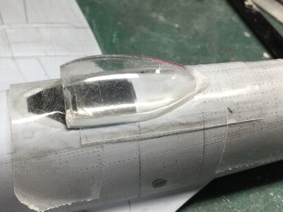 It is difficult to see because it is transparent, but 0.2mm plastic sheet is put on the fuselage, it is fixed with scotch tape, and the canopy clear part is glued on it. |
 0.2mm plastic sheet is shapen. It might be better to make the lower side straight on the rear half. |
|
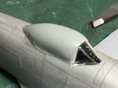
I plan to fix the wooden mold and heat press again. But before that, I'll scratchbild the windscreen. Because the kit windscreen is too small and the width of the front window is narrow.
|
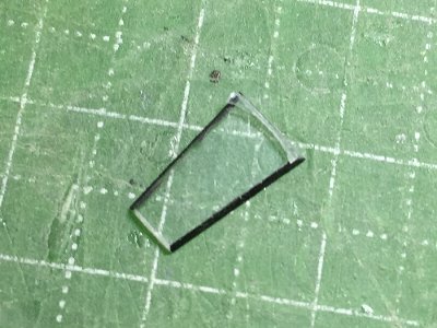
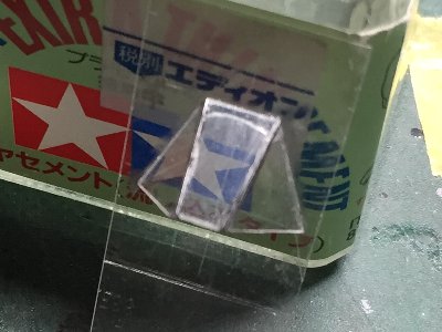
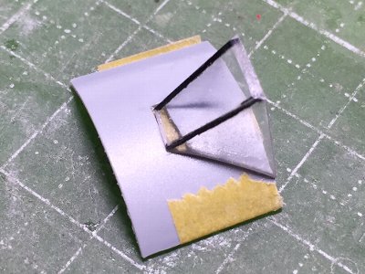
 Cut out and shape each window part. Mark the position of the frame on clear plastic sheet. |
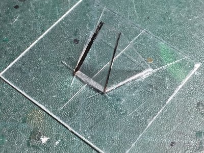 Each window is glued with thin liquid cement. |
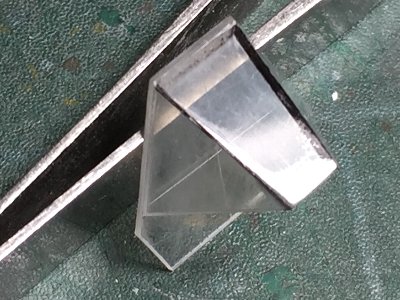 CA glue is polished out and the surface is polished. The cross section of the front wingdow looks black. It can be recognized by reflection of light. |
 The excess portion is cut out. Then the parts is set on the fuselage to check its size. |
|
|
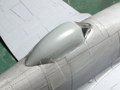
 0.4mm plastic sheet is glued inside in advance. This is due to a margin when sanding the upper curve. |
 The rest of the procedure is the same. |
 The latter half of the plane shape is sanded to be more linearly sharpened so that the tail became sharp. Then 1.0mm acrylic sheet is heat pressed. |
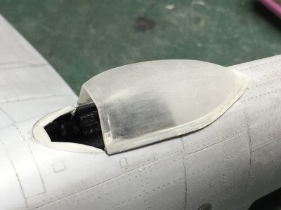
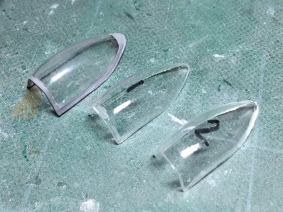 Left, the previous hood. Middle & right, new hoods. One is spare. |
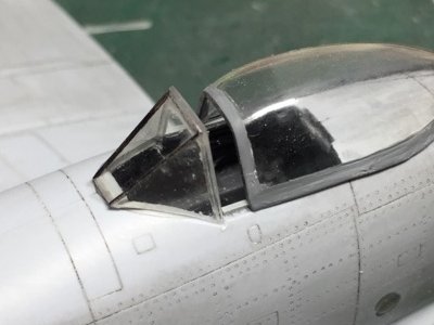
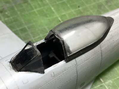
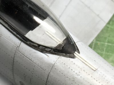
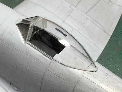 The hood is roughly cut out and temporarily placed on the body. The rear end of the windscreen is slightly wider. Pay attention to the sharpness of the rear edge of the hood. |
 In order to cut the rear end of the windscreen, plastic sheet is bent downward and is glued as a reinforcement. |
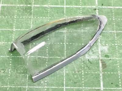 0.5mm plastic sheet is glued with CA glue as the frame. The adhesive surface is painted black with an oil-based marker pen. |
 The frame is sanded and the edge is attached with 0.2mm plastic sheet on the rear half. The frame is painted in black to check the finishing condition. The windscreen is glued with thin liquid cement. |
|
|
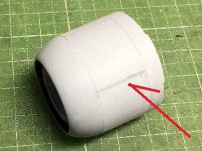
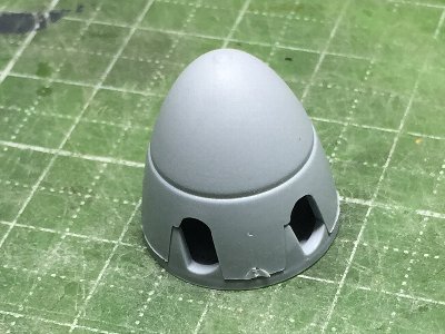 This is the kit spinner before correction. The tip is roundish and the angle of the propeller hole is too steep. This kit part will be sanded with a hand router. |
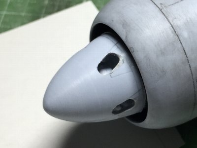 This is corrected spinner. See the pointed tip. Plastic sheet is glued on the edge of the hole. The assembly position of the kit spinner is about 1mm ahead of the correct position. The image is in the correct position. |
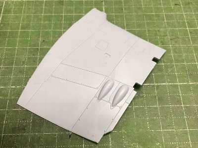
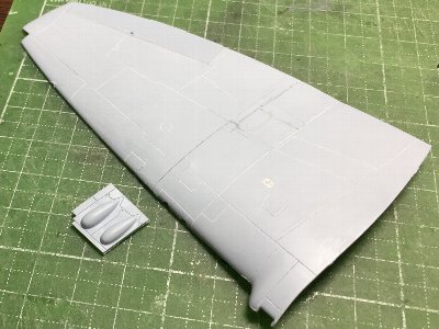
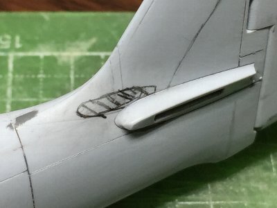
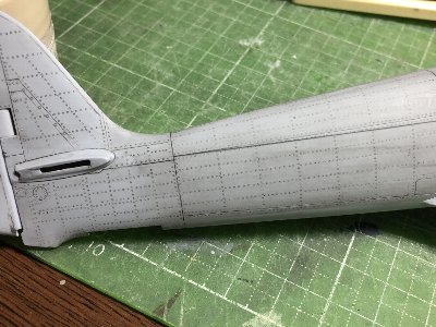
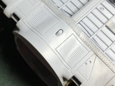
 Gun blisters which was cut out before are glued on the wing. Panel lines are engraved with the transparent plstic sheet template (can you see?). Rivets on the fuselage are engraved as well. |
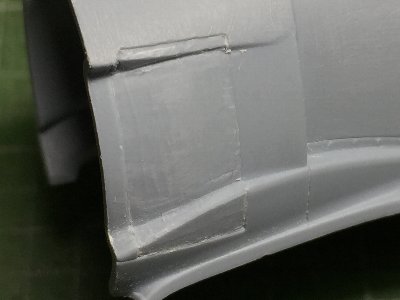
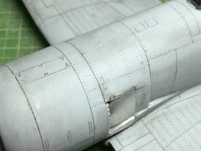 The cowling is glued and the step gap is sanded. This sanding work is a rather difficult, because the gluing line is in a concave bent line. Rivets are engraved after the correction. Fasteners on the fuel tank are done with a #3 beading tool. |
 The exhaust pipe is from the kit. The edges are thinned with a knife. |
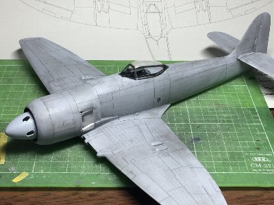 So finally I can see the whole shape. |
 The blister made of plastic sheet is added. Rivets on the radiator are engraved with a needle. |
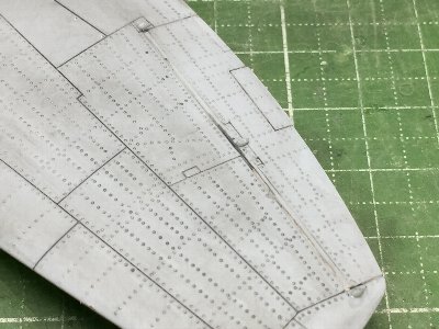 Three blisters are added as the aileron hinges. The shape of each blister will be finished after that. |
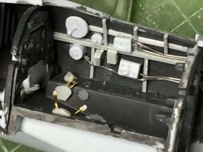
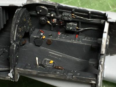
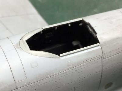
 The slide rail (0.3mm ü~ 2) and the seal (0.5mm) are added to the rearward the cockpit. |
 The rear end of the hood is cut in accordance with the rail. |
|
|