Hawker Sea Fury Airfix 1/48 part-2
|
|
|
|
|
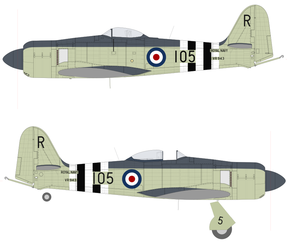
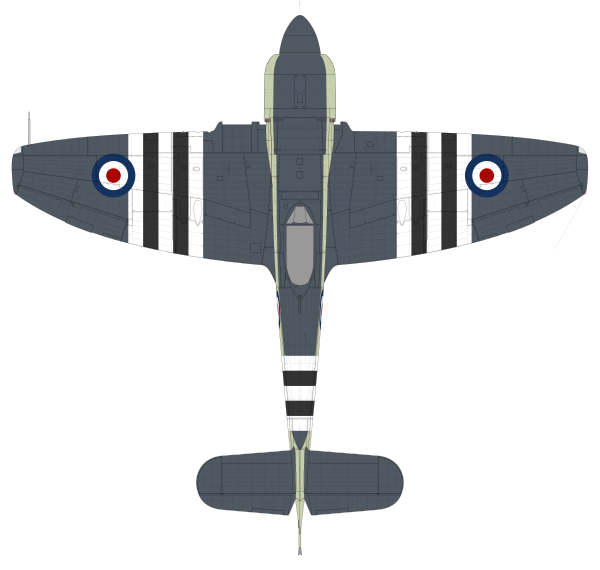
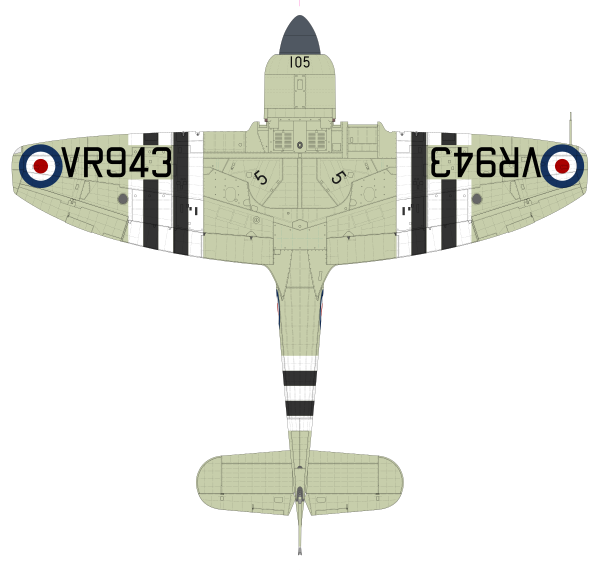
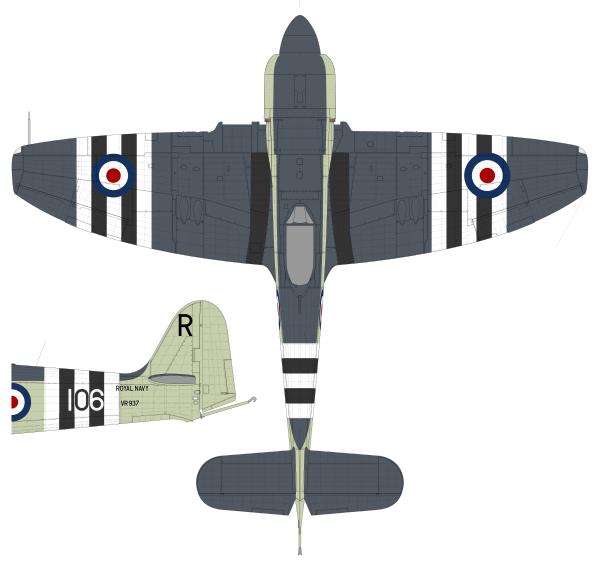
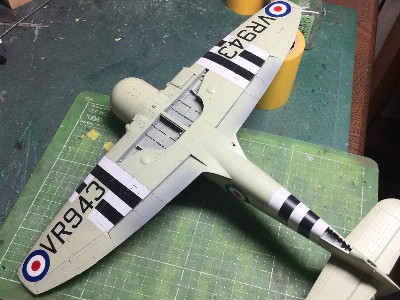
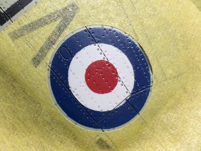
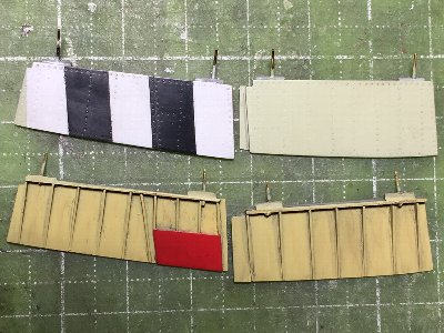
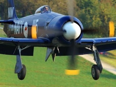
This way of markings is not the same for every Sea Fury. Even within the same unit, there may be different cases for each aircraft. The lower picture is example of these variations. The VR937/106R is the same 804 Squadron, and this aircraft's wing band is shown on the port side of this top view. As it can be seen from the comparison with the above image, the position of the black and white band is greatly changed. I feel that the wing band is closer to the inside in the early days of the war, and more outward in the later stages. This is also another variation on the starboard wing in the lower picture.
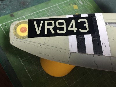
As for the lower surface, the band is often painted avoiding serial number, but there are also those that are painted over serial, or those painted only on the upper side of the wing and not on the lower side, and those that are painted without on the aileron. The band of the fuselage is roughly divided into two examples in which the rear end is immediately before the tail gear door (upper picture) or the rear end is the front panel line (lower picture). This is also applied to avoid the aircraft number, the machine number is in the opposite color of the band. Also the typeface, size and location of the aircraft number are also different. On the other hand, each roundel and serial may basically be factory painted (excluding the early production aircraft that was repainted from the previous paint scheme), so they are generally common. The fuselage roundel is 30 inches in diameter, the wing is 35 inches, the lower wing serial is 24 inches height, and the black and white band is 12 inches width each. However, if you look closely, there are variations in delicate positions and typefaces. |
|
|
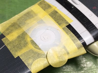
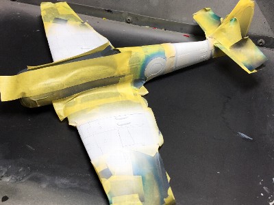
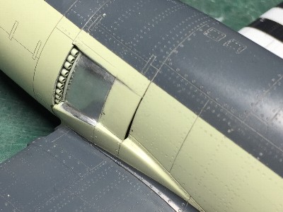
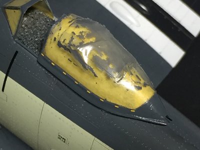
 Windows are masked with Scotch tape. It is cut after pasted. |
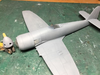 Surfacer is sprayed. |
|
|
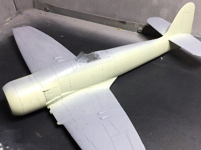
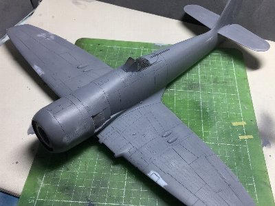 Defects and forgotten works are repaired. After that, surfacer is sprayed as the paint base. |
 The color image is checked. The EDSG on the starboard side was used for my 1/72 Seafire XVII, the port side is for Sea Fury. |
|
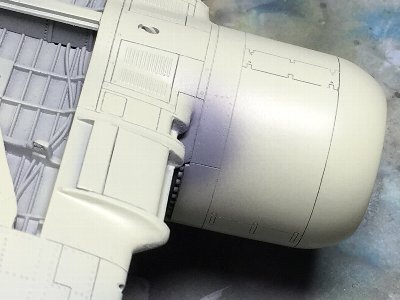
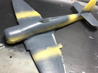
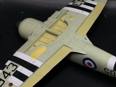
After the sufficient coating of surfere is done, color painting starts from Sky of under side. Then I found a new defect. I've become forgetful recently. I don't want to be old. Anyway, I repair and touch up. If a plastic surface appears in a sanding work, be sure to spray surfacer and then spray color paint. This technique is important. Next, Sky is masked and EDSG is sprayed. I want to make the thicknes of paint layer thinner, so I also mask the band and roundel and paint them in side-by-side. Especially if the fuselage band is not masked, the gap of EDSG and Sky will be visible throuth white paint. |
 First, Sky is painted. |
 Surfacer is painted on repaired portion. |
 EDSG is finished. |
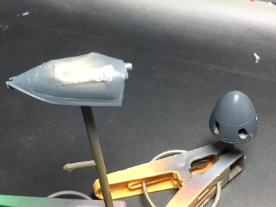 The slide hood and spinner are painted as well. Panel line and small holes are added to the spinner. |
|
Therefore, the foundation layer of surfacer is important. Surfacer can make a uniform coating layer even with the same thinness (because there is little clear content?). If normal color paint is sprayed on the surfacer, the paint will not clump. Thus, this painting method results in the thinnest coating layer. Although it is paradoxical that painting with surfacer becomes thinner than without surfacer. When the thickness is sufficient to obtain sufficient color with only color paint, the clear layer becomes thicker, and as a result, the total layer becomes thicker. Another advantage of thin paint is that it can be sprayed even on rainy days. I have never experienced fogging. Conversely, if you can't paint on a rainy day, the paint is too thick. The concentration is adjusted with the feeling of flowing by the stirring brush on the edge of the cup. So the exact concentration is unknown, but the cup can be seen through the paint. Air pressure is quite low. The nozzle does not open very much, and a narrow area is sprayed. The amount of spraying is that the painted surface just becomes wet. It is not enough to get wet. Paint is forcibly dried with a dryer and sprayed again several times.
|
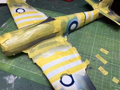
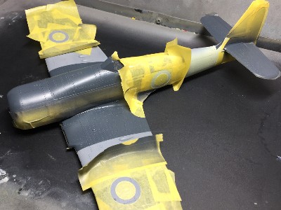 Masking for blue. In order to prevent spilling, the edge of the masking tape is folded. |
 Blue has been sprayed, then masking for white is applied. |
 White has been painted. It is stopped at just balance between coloring and the thickness of the layer that does not fill the rivet. |
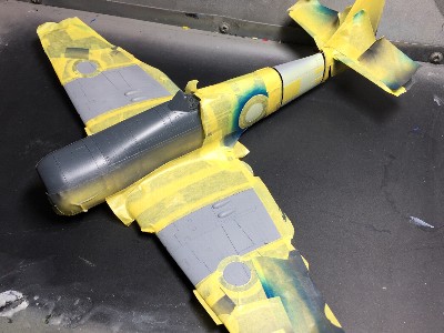
 In the middle of the mask for the black band. White is an expanded color, so I make it thinner than black (about 0.3mm), it looks in the equal width. |
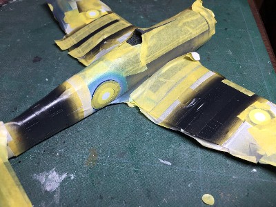 This is masking for red circle. It is 5.6mm in diameter, so it can be cut easily with my tuned-up circle cutter. |
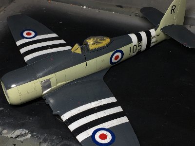
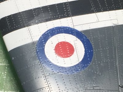
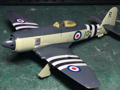
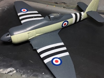 All masking is removed. Roundel and identification band are finished. |
 Masking sheet for the serial number is cut by a cutting machine. |
 The serial number is finished. |
 Flat clear is over sprayed, and the steps on the boundary and orange peel of the paint are lightly polished with Mr. Laplos # 6000. |
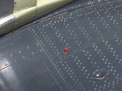
 Lightly washing with powdered pastel + soapy water is applied. |
|
|
 This is masking for the correct blue circle. |
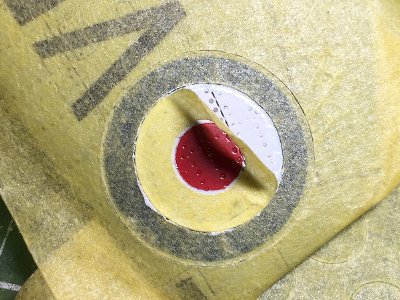 The wrong blue portion has been removed with a knife, and white has been painted. This photo shows masking for red. |
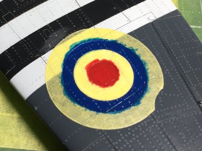 Blue and red are painted with a brush. |
 Next day, steps are polished out with Mr. Laplos. After that, flat clear is over sprayed. |
|
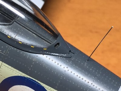
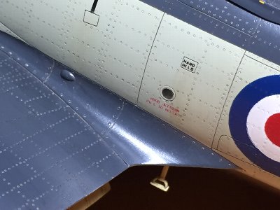
Dry decals are applied. |
 These letters are all dry decals. |
 The yellow dots are kit decals. |
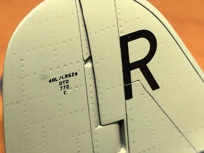 These cautions are dry decals as well. |
|
|
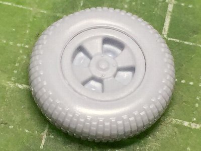 The kit tire is good balance of tires and wheels. Block reproduction is not good at the limit of injection. It maybe a little thin. |
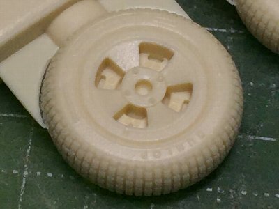 Barracuda resin. The wheel is too big. When it is lined up with the kit, the imbalance is remarkable. |
|
There is a 3D printer in such a case. The rubber part of the tire can be cut out from the resin parts, but I try to model 3D prints of the tire. First, I designed a single column of block pattern, and the next block column is a horizontal flip of it. Then, they are deployed on the circumference of tire and cut out the tires surface. Looking at photos of the actual aircraft, and I reproduced the number of blocks as they are. Next, the problem is the printing method. When the tire is placed on the slicer, there are discontinuous points located on the lower side on each individual block which cannot be printed well. To avoid this, it may needed to add supports to individual blocks or modify the model so that it do not have discontinuous points (such as a way of cutting grooves). As a result of various trials and errors, it seems that the tire should be placed horizontally and designed so that the groove is cut horizontal (lower right image). |
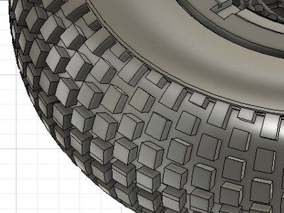 When blocks are designed as the actual aircraft, it looks like this. The wide groove is because the block swells during printing. This is the fate of LCD printers. |
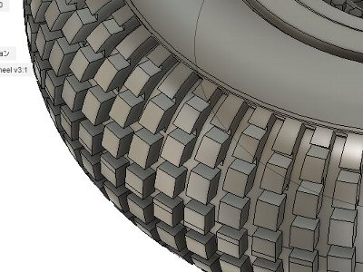 When blocks are designed to print horizontally, grooves are cut horizontally as well. |
|
The wheel also seems to be good in a horizontal output. If the layer thickness is 0.05 mm, stacking marks will stand out. The top image is 0.02mm. Maybe it is better to print with different parameters in tires and wheels. The wheel on the other side is also made. |
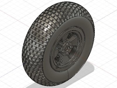 3D model of tire and wheel is finished. |
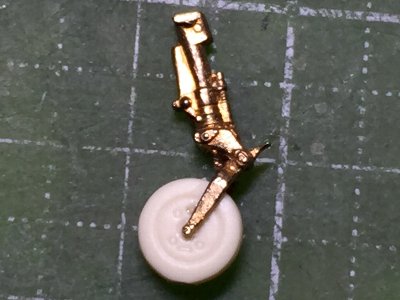
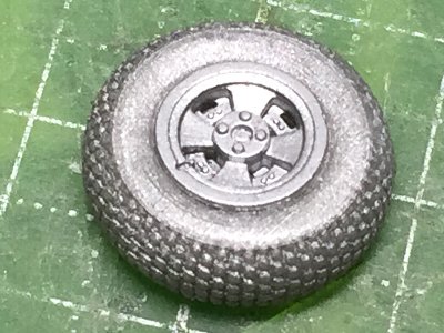 Trial print. Silver paint is sprayed so that a mold is easy to see. Its details is more crispy than kit parts. |
|
|
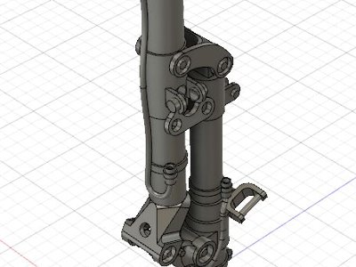
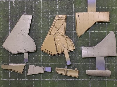
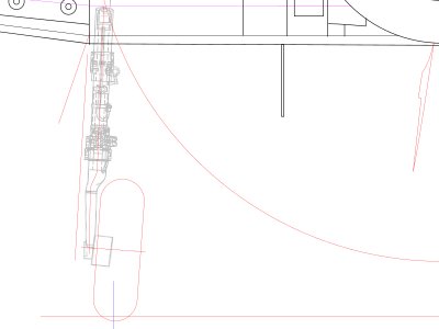
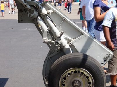 Early type. The gear cover is also different. There is the panel inside and no blister outside. |
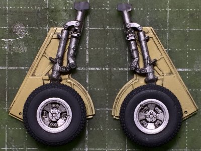
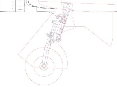
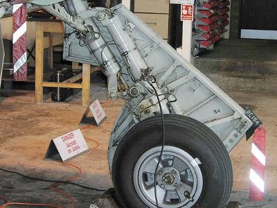 Late type. There is the oreo at the top of the fork. For this reason, the front column is thick. The frame arrangement of the cover is also different. There is the blister outside. |
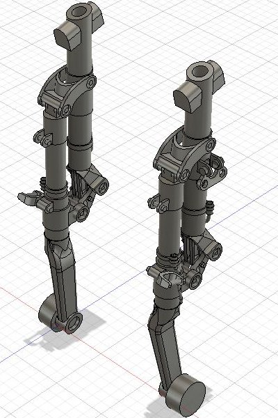
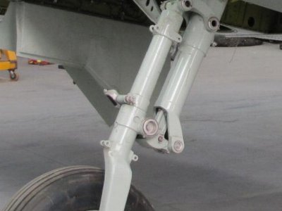 Early type. The so-called ordinary oreo is hidden in the rear column, and the link that connects the front and back columns pushes the oreo up. |
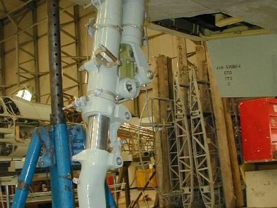 Late type. The oreo of the front column is extended. |
|
The curve at the top of the fork is created with a basic shape by Sketch and Extrude and corners are rounded with Fillet, but when it comes to such a complex shape, Fillet can not work well. Since some orders cannot be done. A file will come into play after molding. The brake line is also integrated. |
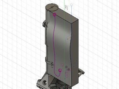 To draw a 3D curve, use Sketch -> Project/Include -> Project to Surface and project the curve to a curved surface. You can Extrude it out as a surface in Patch Work mode as well. |
 Sweep the circle along the purple line on the left. Move the resulting brake line and attach it to the column. |
 |
|
Then you may take away. Since the brake line is designed as the separate body, if it is unnecessary, it is turned off and STL data is output. Also, although it is off in the screen, there are spare parts such as catch rings.
|
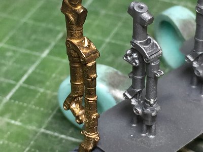
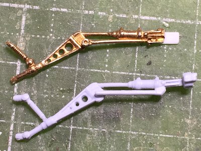
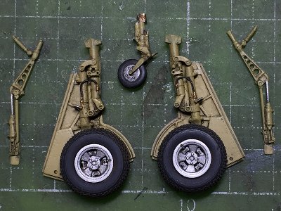
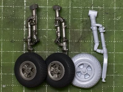 The gear leg and wheel are painted with Mr. Super Fine Silver. Weathering is lightly applied with Tamiya Weathering Master. On the right are kit parts. Pretty poor. |
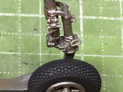 The catch ring looks like this. The details is not so crisp as an injection kit, but this is the limit of Photon. |
|
|
 The left is Barracuda. The right is my 3D part. |
|
|
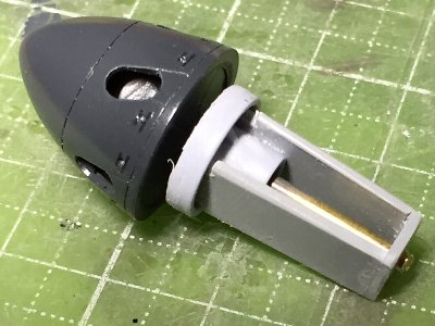 The light blue part is the spinner base part of the kit (after processing). Originally, the diameter of the kit base part is the same as the spinner. But after cutting, this part disappears. |
|
|
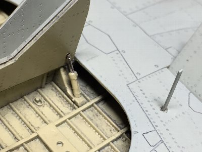
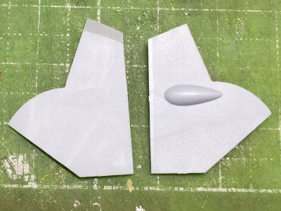 Right, kit original. Left, after correction. The blister is sanded off and extended the top by 2mm. |
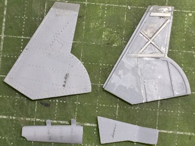 Additional work is almost finished. Rivets are engraved with a #1 beading tool. The inner plate area is extended with 0.2mm plastic sheet. |
|
|
 Work finished. Attaching joints are glued on the front edge. The overlapping part is made of 0.2mm plastic sheet. |
|
|
 Upper, Barracuda. Lower, kit. One hole is added on the triangle plate. |
 Barracuda including tires. |
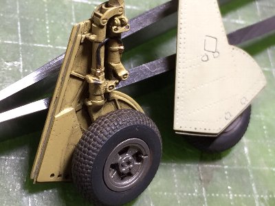
 Details are added on the cover and they are painted. Handles made of plastic sheet are temporarily glued where it cannot be seen after completion. |
 The main gear leg and cover are glued tightly. However�E�E�E |
 Hawker Yellow is the correct color for both the leg and link. They are masked and repainted. Sigh. |
 The brake line between the front and rear column is also added with 0.3mm lead wire. |
|
LCD resin is very weak and easy to break. If there is no countermeasure, it will break at the root. Therefore, 0.8mm brass rod is inserted into the rear column from the top to the middle (the length is about 1cm). The hole is opened at the time of 3D design. As for the middle - lower part, load is shared to the gear cover part. For this reason, the column and cover are glued thightly to each other with CA glue where they cannot be seen from the front. The side of the tire is also glued to the fork with a spacer. The wheel axle alone is insufficient.
|
 Mask and paint. Since it is painted in five colors, it is quite cumbersome. Red is Mr.color GX3 + a small amount of C45 Sail Color. |
 The gear & flap housing is also Hawker Yellow. It is 2:1 of Sail Color and Zinc Chrome Yellow. |
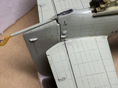
 The gear is glued on the wing. The completion will be soon. The leg angle will be described later. |
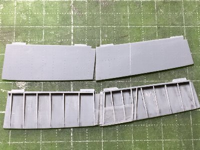
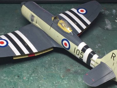 The flap can't be seen unexpectedly. |
|
|
 |
|
|
 |
 |
|
|
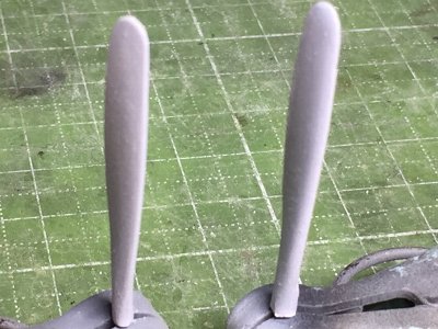 Right, kit. Left, thinly sanded and the curved front edge shape is corrected. The blade width is not changed. |
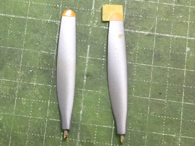 The tip yellow is painted with side by side. Undercoat with silver is painted to prevent see-through. The blade is painted in black with 20% white. |
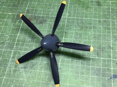 Blades are glued to the spinner, paying attention to the pitch. The caution is from kit decal. Clear is oversprayed and the surface is polished. Finally, flat clear is sprayed. |
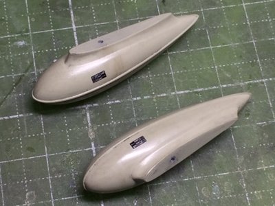 The wing tank is a kit part including decals. Weathered with Tamiya Weathering Master. It is correct that the black square is larger. |
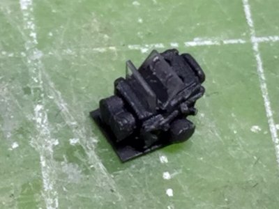
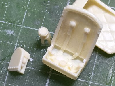 The seat, compass and bulletproof plate are Barracuda resin parts. The upper part of the seat harness is not included in the set and is added with thin lead sheet. |
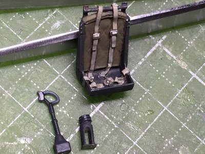 Rods are added to the back of the seat. It is slightly different from the actual aircraft. The control stick is a kit part. |
 The gunsight is also Barracuda. The glass is 0.2mm clear plastic sheet. The thin edges is painted with dark gray so as not to stand out. A small tip of plastic sheet is glued on the bottom of resin part, and is glued to the cockpit with liquid cement. |
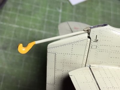 The tip of the hook is a kit part. Expression of the cross section is good. I don't know it was painted actually in yellow. The rod is a 1.0mm brass pipe. |