Supermarine Spitfire Mk.Ia Tamiya 1/48 part-1
|
|
|
|
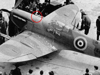
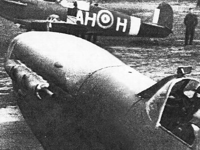
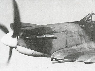
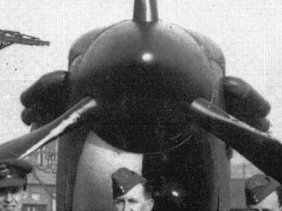
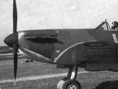 This is a recorded photograph at the time of WW2 (flip horizontal). This is the correct nose outline. |
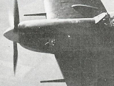
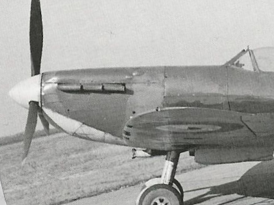 Same as on the left (flip horizontal). Its shape is like a downhill forward from the fire wall. |
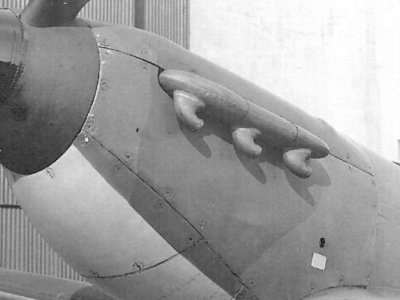
 An existing aircraft that has been restored (flip horizontal). It can be seen that the shape of the upper cowl is different. |
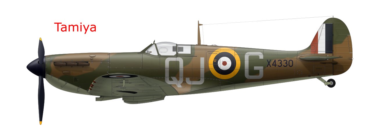
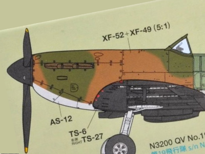 Illustration on the box of the kit. The shape of the kit is also like this. |
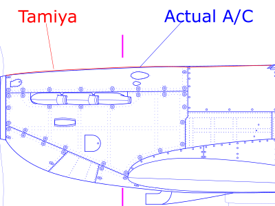 Red is the kit. Blue is the actual aircraft. |
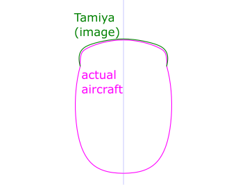 The cross-sectional view at the position of the pink line in the left figure. Pink is the actual aircraft, green is the kit . |
 It can be seen that there is a straight line from the upper cowl to the fuel tank. (The image is flipped horizontally.) |
 On the other hand, the bulge of the cylinder head is slightly excessive, and it has an S-shaped curve from the upper cowl to the fuel tank. |
|
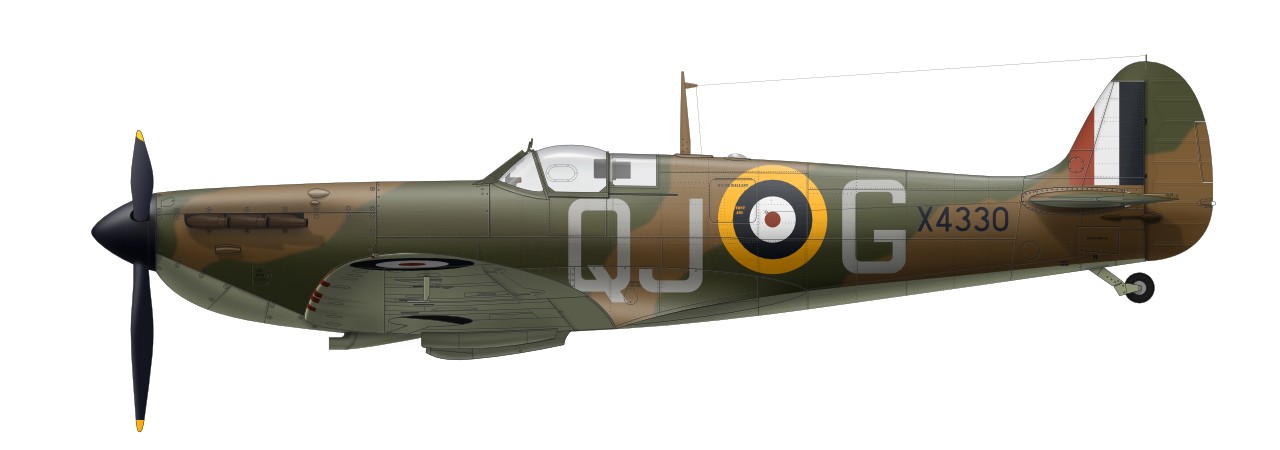
In the above figure, the lines overlap and it is difficult to understand, so let's compare with the illustration. The top is the actual aircraft (blue line in the above figure), and the bottom is the Tamiya kit (red line in the above figure). You can see it in the slide show. The actual machine, that is, my side view, faithfully reproduces the fuselage frame coordinates, various dimensions, etc. in the manufacturing drawing, and is verified with the photographs at the time of WW2. So I'm 100% confident about the side shape. Actual Aircraft |
|
|
 |
|
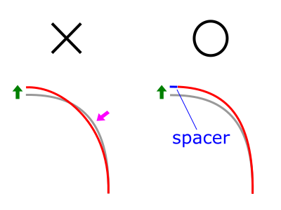
Even if the two illustrations are compared, the difference is subtle. Therefore, a typical modeler can build the kit as it is. However, this cannot be overlooked by modelers who identify themselves as Spitfire enthusiasts. The point is the bending at the fire wall. The image of the kit is from Mk.IX. So, depending on how much you love Spit, you can modify the kit. However, for perfection, I recommend not only scraping the top of the upper cowl, but also raising the firewall. At this time, simply bending the parts and lifting them up is not enough. This is because the cross section at 2 o'clock and 10 o'clock is dented as shown on the left in the figure below. In this case, the lateral bulge of the upper cowl is relatively emphasized, and it goes in the "dissimilar direction". To prevent dents, it is necessary to insert a spacer with the same width as the height to be raised as shown in the figure on the right. |
 |
|
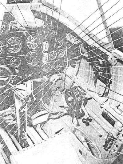
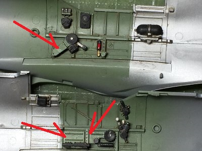
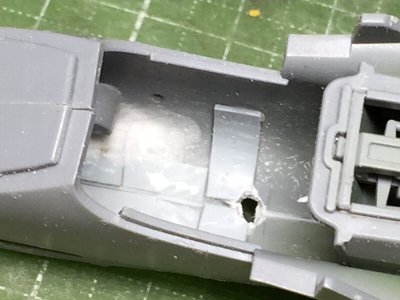
Also, some painting instructions were questionable. From the photo of the official manual, the box behind the port trim tab operation dial and the front part of the starboard landing gear operation column should be green gray instead of black (red arrow in the image below). Other than that, it is difficult to distinguish from monochrome photographs. For reference, let's take a look at the cockpit photo in the pilot note of Mk.Ia . The brightness of the port box is unknown in this image, but it is bright in the Mk.II and Mk.V manuals. |
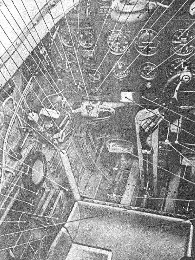 As for the trim tab dial, this type may be correct. My work has followed the kit instruction. |
 Also pay attention to the brightness of the single bar rudder pedal and the seat that seems to be green gray. |
|
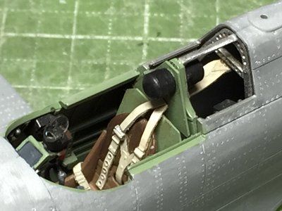
Well then, I started working on the cockpit. The paint color of the sheet of the early Mk.I model should be considered. The possibility of grayish green or black cannot be denied, but the possibility of brown cannot be denied either. The sheet was painted with a mixture of self-made Dull Red and Dark Earth. The backrest was Red Brown. Gray green is Mr. color C364 Aircraft Green Gray. |
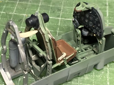
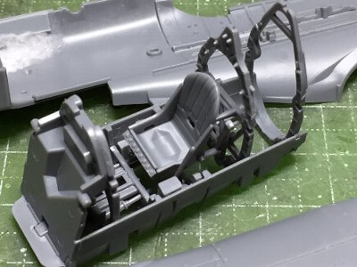 The cockpit was assembled. |
 Details are painted like this (see red arrows). I painted all the throttle columns in black, but the instructions may be the correct answer. |
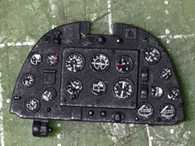 The decal was cut out with a punch and pasted. Then clear paint was dripped. |
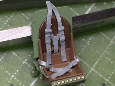 The bulletproof plate was a 0.3mm plastic sheet. It was easy to glue to the back of the sheet. The shape was the same as Mk.IX, but it was not confirmed. The seat harness was from Finemold's Nano-Aviation series. |
 The positional relationship is as shown in this image. The pin on the rear frame of the seat was cut a little. |
 The seat belts behind the bulletproof plate were cut and glued separately. The head pad should be a little higher. This was fixed later. |
|
The seat harness was from Finemold's Nano-Aviation series. These were too wide, so the width was narrowed by cutting off both sides by 0.1 mm. There was a convex mold on the edge, so I used it as a guide to push it through with a design knife. The holes were drilled. The headpad is higher than the equipment behind (see my illustration). The slanted square in front of the gunsite mounting base is a light blocking filter, so the inside should be transparent (or colored glass).
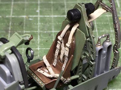
According to the aforementioned Spitfire Notes, plastic seat was introduced in May 1940. Prior to that, it was made of metal and was painted gray-green or black. Even after the introduction of the plastic seat, both continued to be used as an alternative. The aircraft which I am building was probably in production after June. So I painted it brown. There was no confirmation. The hexagonal dent on the seat bottom is a feature of the plastic seat. I haven't seen it in the metal seat, and I can confirm whether there are no dent or dent spreaded to both side.
|
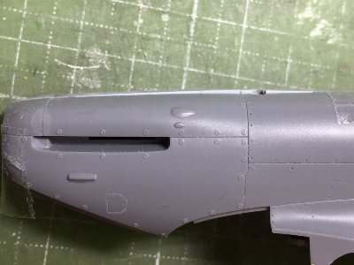 While leaving the port parts as they were, only the starboard parts were lifted and the spacers were glued. The intention was to sand it to the correct height after raising it excessively. |
 This was also in a state where only the starboard side was corrected. Correcting one by one in this way makes it easier to control the amount of correction. |
 The port side has been modified to match the modified starboard side. The left and right fuselage are glued together and roughly shaped. |
 Reinforce the cut line in the panel line of the fire wall with a plastic van from the back. |
|
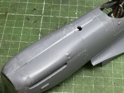
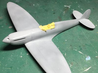
The base for sanding work was completed. I would sand the cowl to be a correct shape. In particular, I plan to boldly sand the bulge of cylinder heads.
|
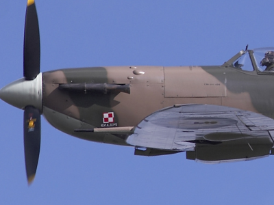
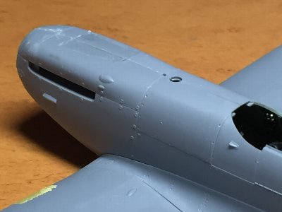
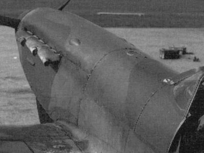
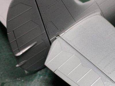
 In this photo, the cylinder head line is slightly bulging. The line near the exhaust pipe is straight. The image is inverted.�B |
 It swells a little looking from this angle. The image of the Tamiya kit does not seem to be bad in this photo, but ... |
 On the other hand, it is linear at this angle. The bulge of the cylinder head also looks much smaller than the kit. |
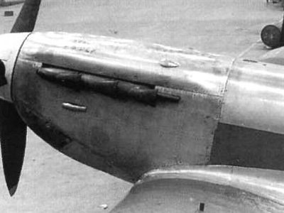 You can imagine the curve near the cylinder head by the highlights. This photo is a different image from the kit. |
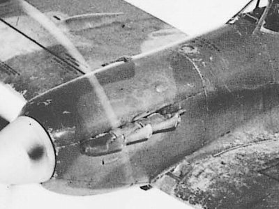 See the curve from the rear end of the spinner to the cylinder head. |
 Pay attention to the line from the spinner to the windshield via the upper cowl and fuel tank. In the modeling of the nose, it was important to reproduce as this image. |
 The delicate cross-sectional shape of the upper cowl can be inferred from the shade. |
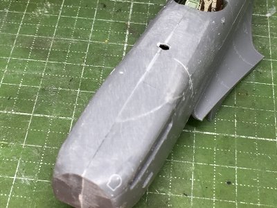
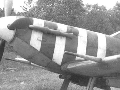 A white belt was painted to make the cross-sectional shape easy to understand. |
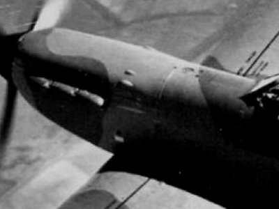
 Notice the line from the spinner to the cylinder head. It's an unexpectedly smooth line. The edge line around the exhaust pipe is straight. The image is inverted. |
 Pay attention to how the cylinder head looks. There are few pictures of this angle, so it's valuable. Looking at this, I feel that the kit upper cowl is a little wide. |
|
|
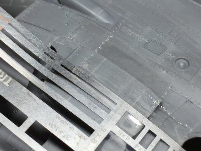
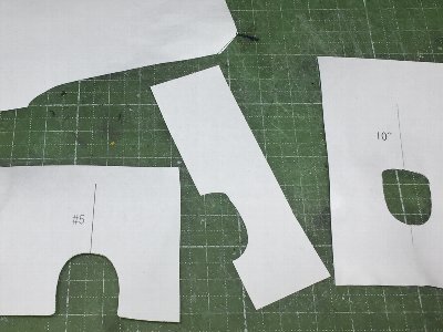 Cross section drawings were printed to make gauges. At the top is a side-view check gauge. |
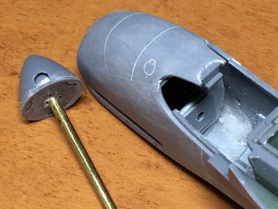 It was important to check the entire image of the nose in the correction works. So the spinner and bareing for the propeller axis were constructed. The lower cowl was also glued. |
 The cross-sectional shape generally matched gauges. Is the image still slightly different? |
 Seen from the side, it looks like this. The upper cowl top line should be a little more straight. |
|
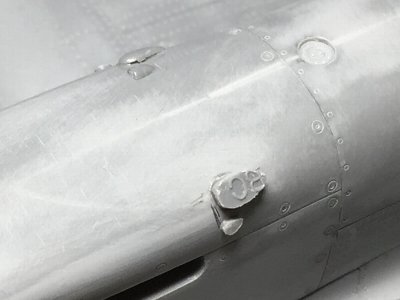
The point to be sanded was the area around the small blister at the rear end of the cylinder head (C). This area should be sanded boldly. Also, the area around the exhaust pipe should be more linear (B). The area from the spinner to the cylinder head is also less rounded (A). I cut out some part of the lower wing, in order to enable to assemble the wing even after the lower cowl was glued. By the way, my old Mk.IIa uses Tamiya's old kit and the nose is almost uncorrected. This isn't better than the old kit, it's just that I wasn't aware of it at the time of production. Of course, the new kit is much more similar, even if it is uncensored. The outline of the old 1/48 is very similar to the current 1/72. So, my 1/72 Mk.I article may be helpful. |
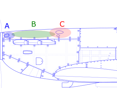 |
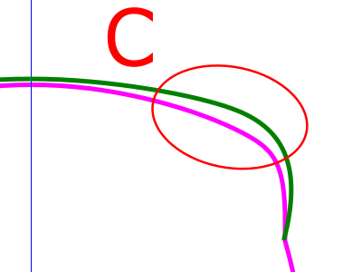 The green line is Tamiya kit. The pink line is actual aircraft. This is the cross section of "C" of the left figure. |
|
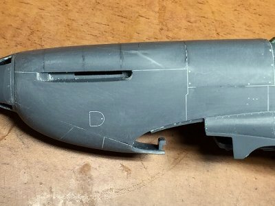
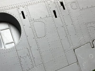
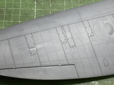
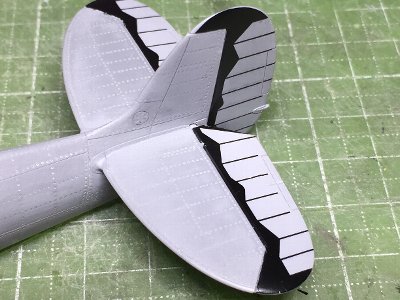
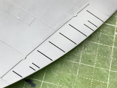
Ribs on the controle surfaces were truly overscaled. I sanded off them and ribs would be depicted with costom made dry decals. The dihedral and the washout angles are correct. The shape of the bulge on the upper side of the wheel well was a little different. I would fix later. See my drawings for the correct shape. Panel lines of the kit were thin and very fine, but they are disappearing due to the above sanding work, so the whole lines were re-engraved. I mainly used a 0.1mm line chisel. Convex molds such as piano hinges would interfere with polishing after painting. So I reproduced them as recessed line. Then, finally I started rivetting. I mainly used #1 beading tool (0.3mm). Fasteners were # 3 or # 5.�@�@ |
|
|
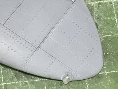
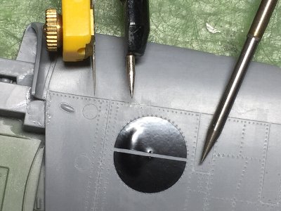 Cutting sheet was cut out a with circle cutter for a guide. |
 Fasteners were #5 and others were #1. |
 Ribs on the aileron were sanded off. |
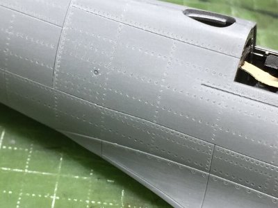 Some rivets on the rear fuselage were convex, but I engraved them with the same #1 beading tools. |
 The navigation light was made of clear sprue. |
 A photo etch template was used for double rivet lines to align the distance between two lines. |
|
|
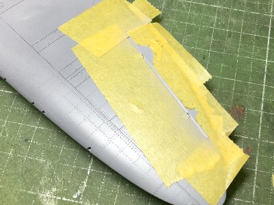
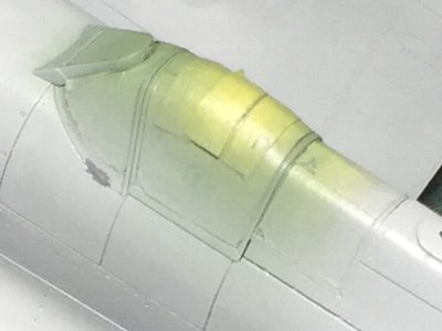
 Thin surfacer was sprayed. |
 The blister was reproduced with a plastic sheet. |
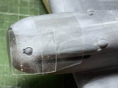 The line of the small access panel disappeared completely due to the shape correction. I made a template and engraved it. Blister is also shaped. |
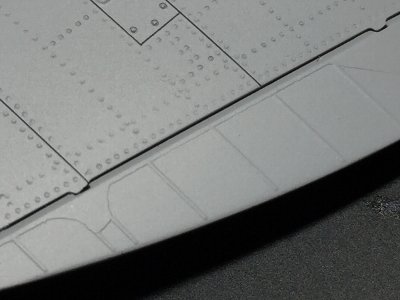
 The rib tape of control surfaces were costom made dry decals. The missing edges were repaired by surfacer with a fine brush. |
 Surfacer was sprayed on dry decals. |
 I forgetted the metal panel area near the hinge. |
 Therefore, it was depicted with surfacer. |
 Finished. |
 The gun sight was a kit part. The shading filter in front of the gun sight can be seen from the front window. The grass portion was painted in dark gray. |
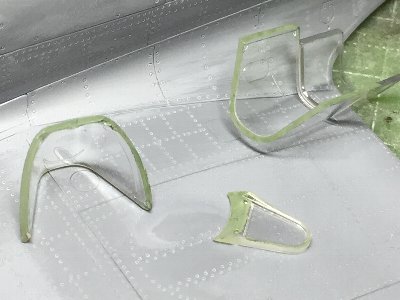 Edges of clear parts were painted in green to prevent from shining. |
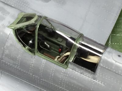 The canopy was glued. Fitting of canopy parts was perfect. |
 I used kit masking sheet. Interior colors were sprayed before surfacer. The inside of the rear fixed window was silver. |
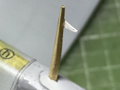 The antenna mast was made of 1.5mm brass rod. The trianguler plete was made of paper. |
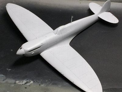 At last, surfacer for the base coat of camouflage painting was painted. |
|
It changed to "QS harness" in 1946. It has no holes in the belt. Each belt was attached to a circular fixture called the quick release box. The end of the belts were fixed to the seat. See my works of Seafury and Seafire FR.47. According to Edgar Brooks, the color of the belt was normal tan during the war and often medium blue(!) after the war. Realy? Details are below. http://spitfiresite.com/2010/04/the-sutton-harness-on-the-spitfire.html |