Seafire FR.47 Tamiya 1/32 part-1
|
|
|
Great thanks to Larry for English text.
|
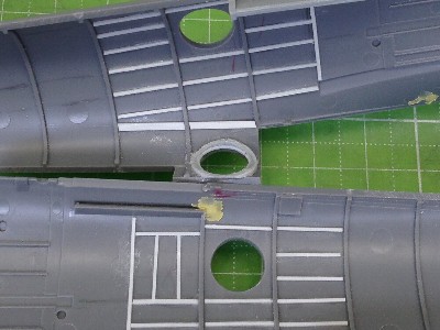
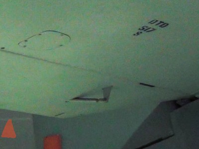 The Mk.22/24 starboard elevator tab rod. This tab may be only for the Mk.22 and 24. Mk.46 and 47 don't have is. | 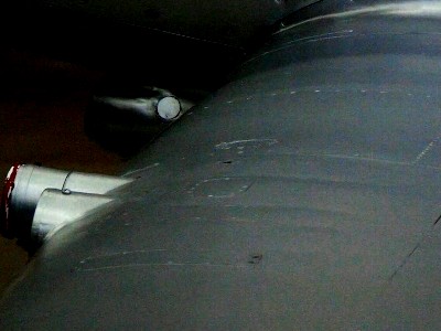 See the ellipse access panel afterward the cannon and two oblong access panel beside the ellipse panel. |
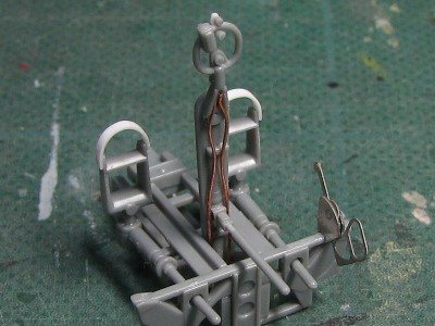
 This photo is the starboard. | 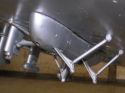 These are the bomb rack and rocket launcher of Mk.18 (?). |
|
Tamiya 1/32 Mk.VIII/IX/XVI As for the outline shape, panel and rivet lines and details, Tamiya 1/32 Spitfires are perfect as well as P-51and F4U. These three kits are the highest standard for accuracy of all aircraft kits.Matchbox 1/32 Mk.22 This kit is too old to comment. If you want to build a correct Griffon Spitfire model, my approach may be better.Airfix 1/48 FR46/47, 22/24 Generally, Airfix kits are excellent. Main parts of the fuselage and wing are correct in dimension. Only a few points should be corrected. That is; the joint line of the nose cowl bulge is incorrect, the nose air intake and lower cowl of Mk.47 are narrow, propeller blade is thin and the shape of the slide canopy is not good.Airfix 1/48 PR.XIX This new tool kit is the best Griffon Spit in 1/48 scales. Main parts of the fuselage and wing are dimensionally correct and good shape. If you build Airfix Mk.46/47 or 22/24, I recommend replacing the nose cowl with this kit nose.Airfix 1/48 Mk.XII Mk.XVII These two kits are basically equal. The outline shape is to fat and macho. The height of fuselage is 2mm (0.08") high. If I build Mk.XII model, I will use PR.XIX kit.
|
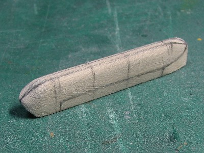
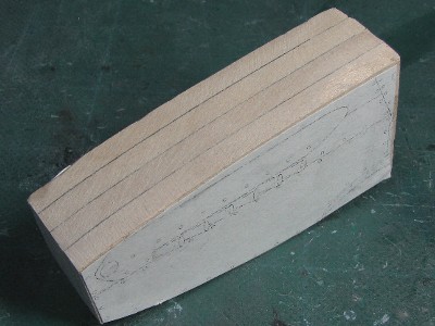 The wooden mold was made of layered 5mm (0.2") thick wood plate. | 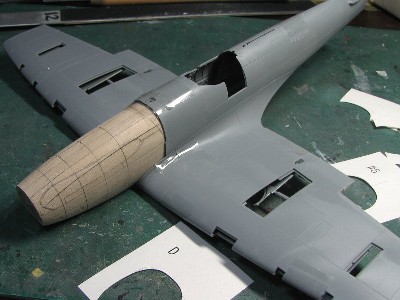 The proportion was chacked with the fuselage and wing. |
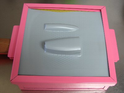 Styrene sheet was heated and formed with this vacuum former at the first trial. The thickness of the side portion became 0.5mm (0.02"). | 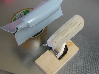 So, after the next trial, heated styrene sheet was formed by hands. |
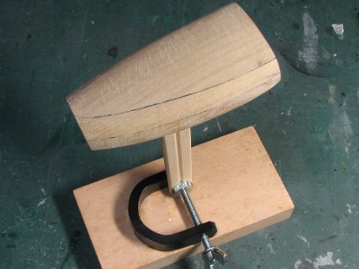 This is the third and final wooden molds. The mold is divided vertically. The left and right cowl panels are formed separately. | 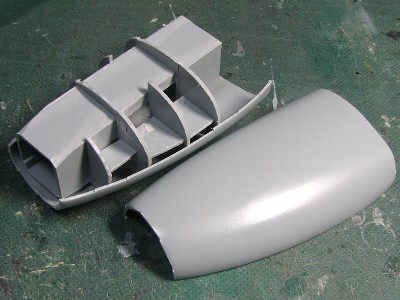 The inner structure was made of styrene sheet for reinforcement, holder of propeller axis. |
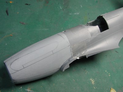 The left and right half of heat pressed nose cowl parts were glued to each half fuselage part. | 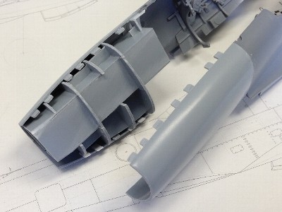 Small pieces of styrene sheet were glue on the adhesive line to hold the precision position. |
|
|
 The tail fin was scratch-built. I used wing parts of Airfix 1/48 Seafire. |
 The camera window was made from 0.4mm clear styrene sheet. I depicted inner frames, but they might be almost invisible from outside. |
|
|
 |  |
 |  |
|
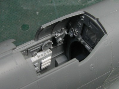
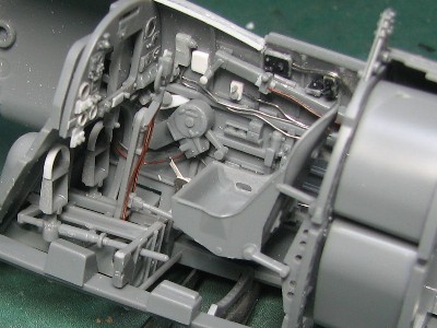
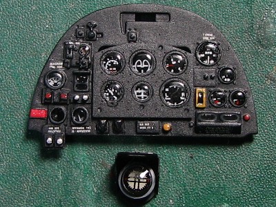
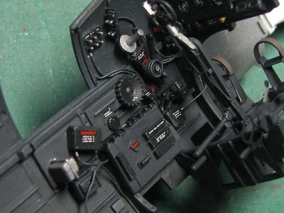
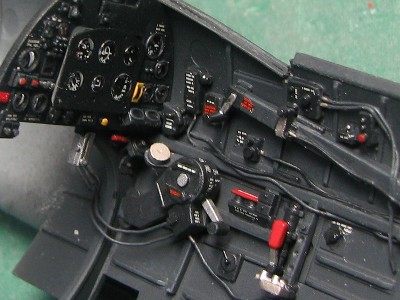
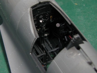
Guessing from some circumstantial evidence, the cockpit of Mk.47 was not painted in interior grey green but black. That is, post war jets are painted black, cockpit photos of existing Mk.XVII of "Warpaint" show upper half is black and lower half is green (I guess the cockpit paint is original), original photo of the inner side of cockpit door looks very dark. So I painted my model with RLM66 black grey. Caution markings were all-sorts of decals. |
 |  |
 |  |
|
|
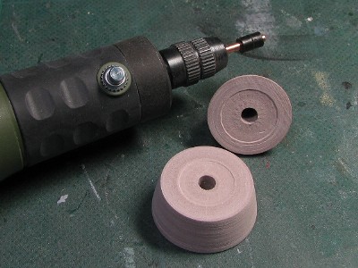 The 4mm (0.16") vinyl cap and 2mm (0.08") metal rod are set to the rotary tool. | 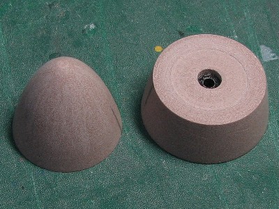 The outline shape was checked with the template paper which was cut from the drawing. |
|
|
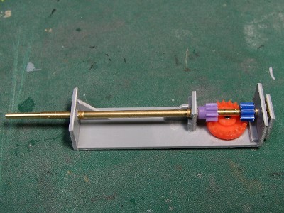 The gear box was made to be inserted from the front end of the fuselage. |
|
|
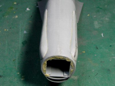
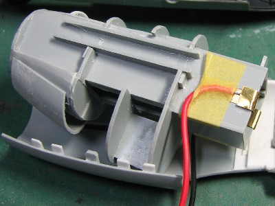 The ceiling of the air intake duct was glued on the inner structure. And battery wires for light-up were connected to the inner structure. | 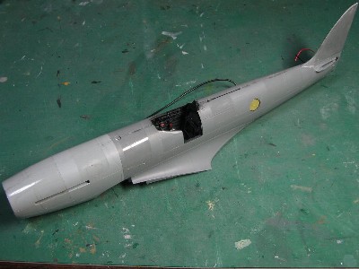 Finally, the left and right halves were glued together. |
|
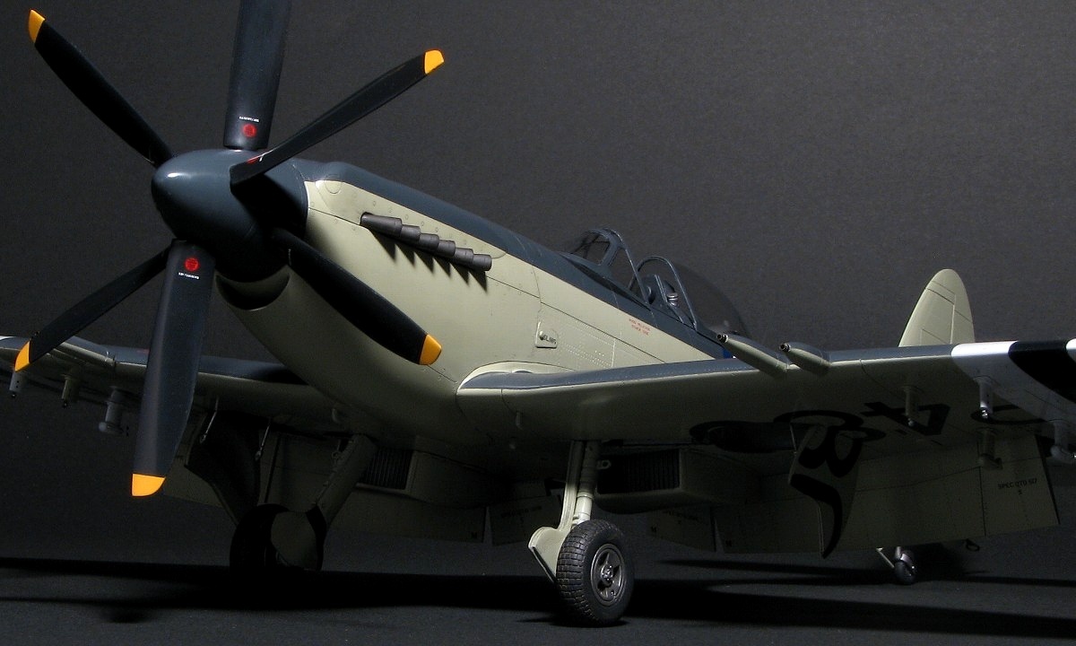
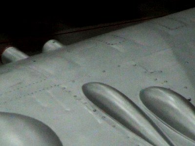
See actual aircraft. |
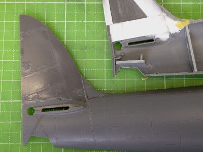
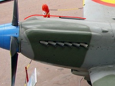 Note the starboard bulge. | 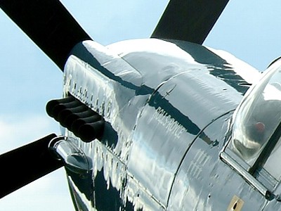 |
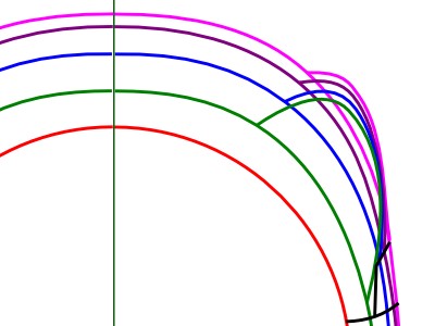
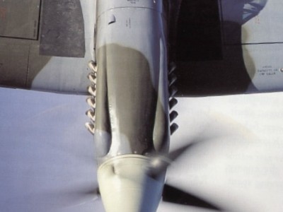 The front and rear end isn't ball shape. | 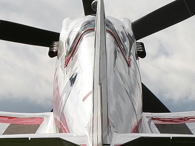 Upper edges of left and right bulges are parallel. |
|
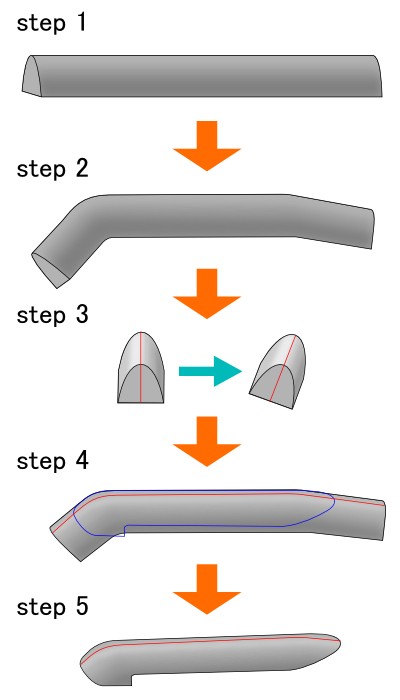
According to this consideration, I made the wooden mold of the bulge. |
 This is the wooden mold of the port bulge. | 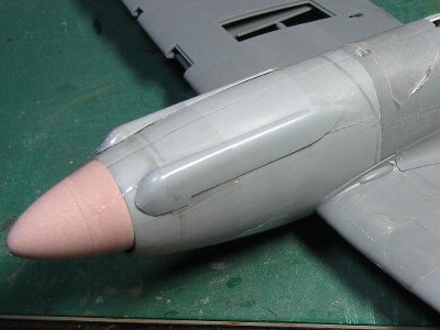 Then 0.5mm styrene sheet was heat formed and cut out. |
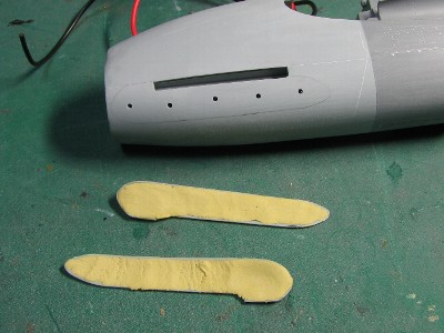 Epoxy putty is used for reinforcement. | 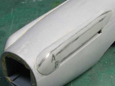 The line A and B are not parallel. |
 See the above photo of the actual aircraft. | 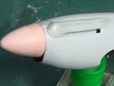 |
|
|