Seafire FR.47 tamiya 1/32 part-2
|
|
|
|
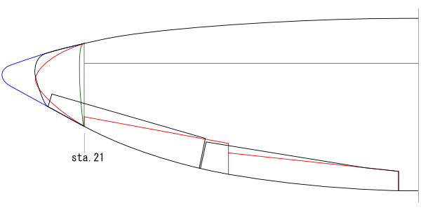
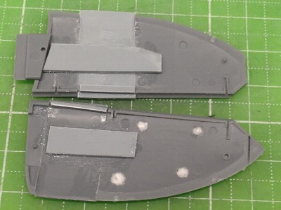
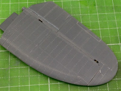
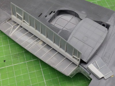
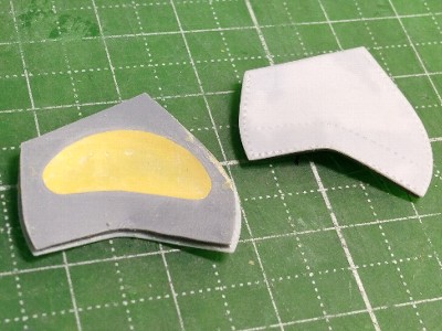
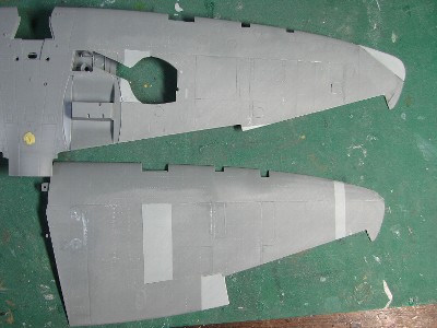 The darker color portions are kit wing parts. The lighter portions are styrene sheet. |
 The carbon fiber reinforcement was glued on the inside to hold 6 degrees of dihedral. |
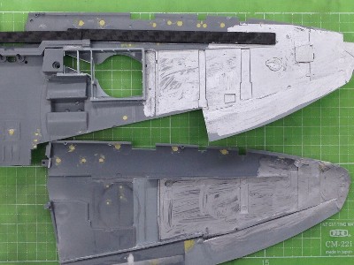
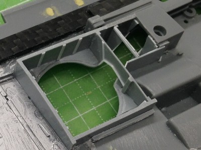 The gear bay was scratchbuilt with styrene sheet. I didn't know details of the gear bay of Mk.47. So I figured it was basically the same as Mk.22. |
 The ceiling of tire house was made of styrene sheet. |
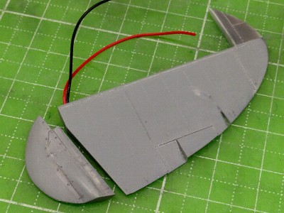
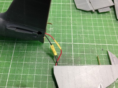
 Navigation lights were lit up by colored LED. Each LED was connected with nylon fiber. g. |
 The tail navigation light is lit up as well. |
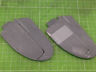
 Then the upper and lower wing parts were glued. At first, the leading edge was glued. Then the trailing edge was carefully glued to keep correct washout. |
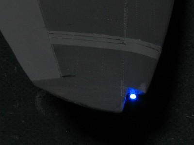 Lighting test. |
 Wing navigation light covers were made of colored acrylic plate. |
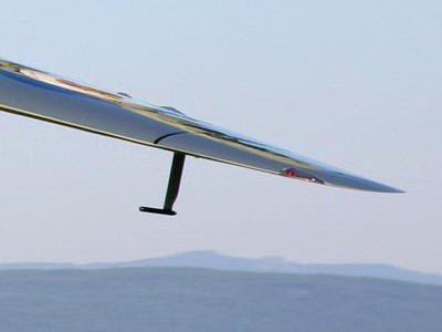 This photo is a restored aircraft. See the sharp edge of the wing tip. The clear light cover is not original. |
|
|
 |
|
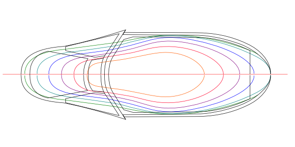
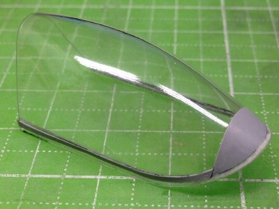
The canopy was scratch-built with heat forming of acrylic sheet. Small size (6" x 6") of 0.5mm (0.02") acrylic sheet was heated on the kitchen gas grill. When acrylic sheet become soft, it was pressed and wrapped on the wooden mold. Heat formed sheet was cut with rotary tool. Each window of the windshield was made of clear styrene sheet. Clear styrene sheet is more difficult for heat forming. But, styrene sheet is easy to glue together. |
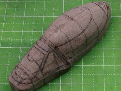 The wooden mold was made from chemical wood. After that, CA glued was applied on the surface of the wooden mold. Then the surface was polished. |
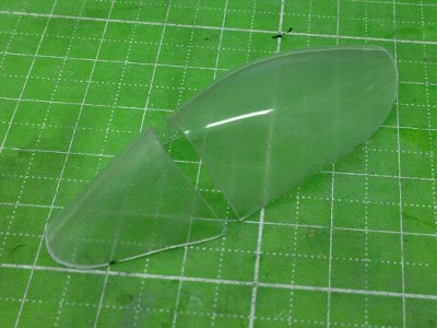 Then acrylic sheet was heat formed. The outer and inner surface were sanded with 800 to 2000 grit sandpaper and polished with rubbing compound. |
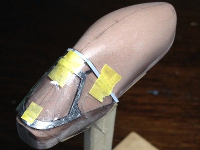
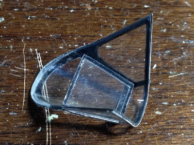
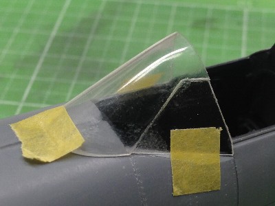 Each window of the windshield was made of clear styrene sheet. The curved front and upper windows were heat pressed, and side windows were not heat pressed. |
 The fringe of the slide canopy was 0.2mm (0.008") styrene sheet. Styrene sheet was temporarily fixed on the fuselage, then the canopy part was glued with CA glue. |
 After that, unwanted part was trimmed. |
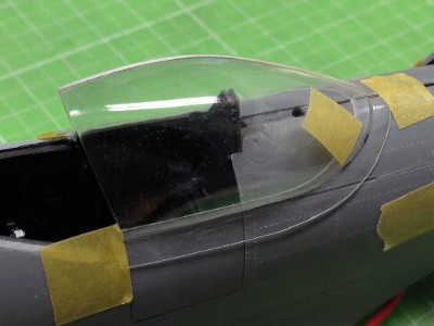
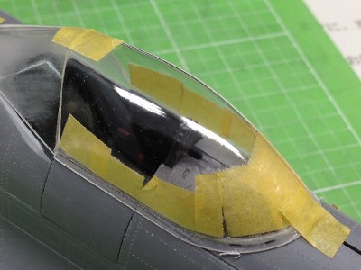
 Other frames were 0.14mm (0.005") styrene sheet. The inside of the frame was painted in black. |
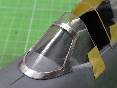 The front window frame was made of 0.3mm (0,01") aluminum sheet. |
 The aluminum frame was glued with epoxy glue. |
 The bullet proof grass was made of 1mm (0.04") thick clear plastic from a DVD case. |
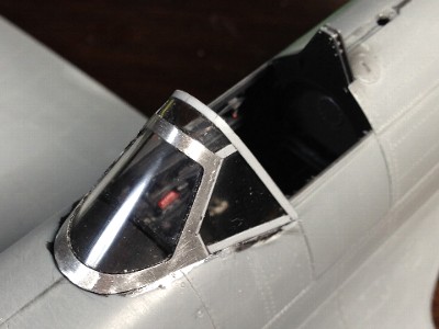 Then the windshield was glued on the fuselage. |
|
|
 |
 |
|
|
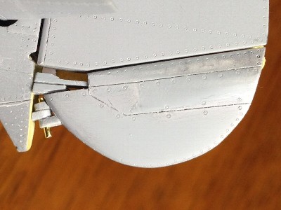
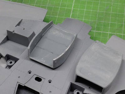 The bottom portion was made of 1mm (0.04") styrene sheet and the side portion was 0.5mm. Styrene sheet was cut and bent. |
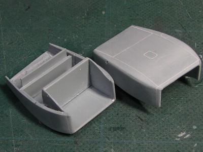 Then each part was glued together. The inner sidewall and radiator box were glued for reinforcement. |
 The fringe was added on the radiator cowl. |
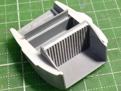 The radiator mesh was cut from 1/24 car model. |
|
|
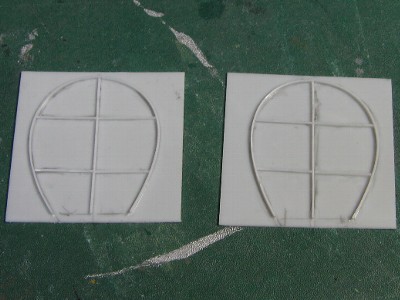
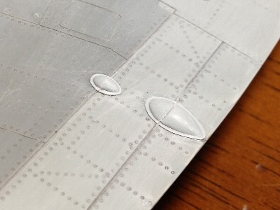
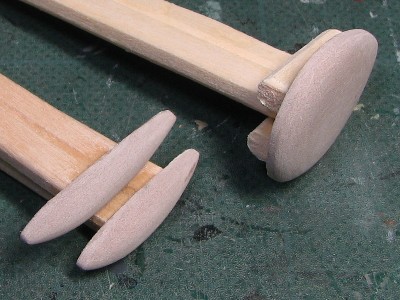 Wing blisters for the 20mm cannons and tire were made of heat pressing 0.5mm (0.02") styrene sheet. |
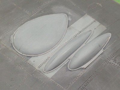 The fringe was 0.14mm (0.006") styrene sheet. |
 Small blisters were made of styrene sheet. |
 |
|
|
 |
 |
|
|
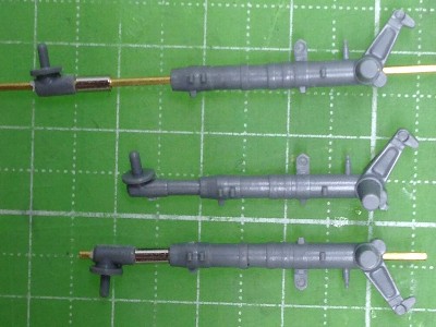
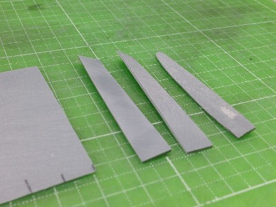 Left; 1mm (0.04") styrene sheet was milled to tapered thickness. Center; Styrene sheet was cut and twisted. Right; Glued sheet was trimmed and sanded. |
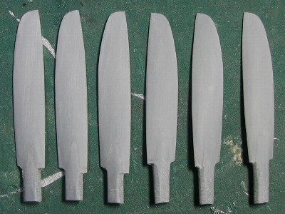 The left three are front line blades and the right are rear blades. |
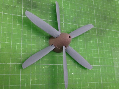 The shape and pitch are checked with the spinner. |
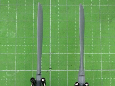 I found that the thickness of the blade root was insufficient. So, small pieces of styrene sheet were glued and sanded again. The left is before and right is after. |
|
|
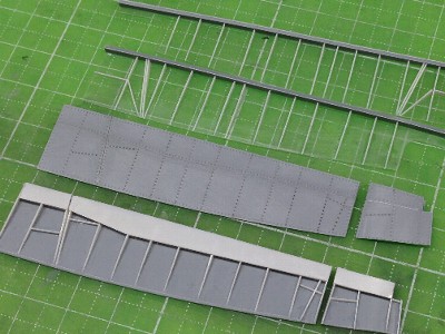 These are flaps and ceilings. The ceiling is made of 0.2mm (0.008") clear styrene sheet. |
 The ceiling was glued to the wing. |
|
|
|
|
 The center is the original kit part. Upper and lower are extended parts. |
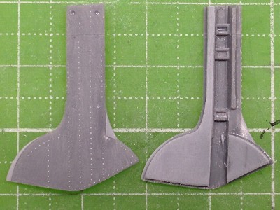 Exact details of the gear cover of Mk.47 were unknown. I referred to Mk.22. |
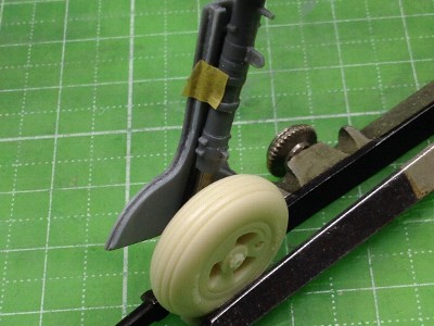 The three slot wheel was from Barracuda Studios. Details are excellent. Unfortunately, the block tread tire is not released. |
 Exact details of the wheel cover were unknown as well. The wheel cover was made of two pieces of 0.5mm (0.02") styrene sheet. Each piece was bent first then glued together in order to fix its curved shape. |
|
|
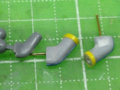 The left is kit's part for Merline. The center and right are the master made of sprue. |
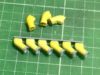 These are duplicated exhausts. |
|
|
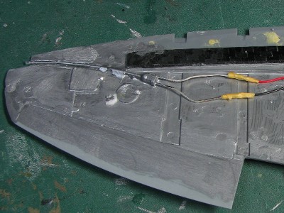
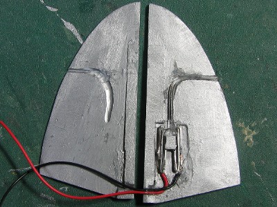
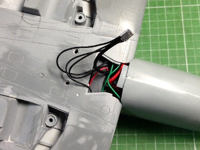 Battery wires were connected with metal sheet. |
 The rear end of nose air intake made of heat formed styrene sheet was glued on the lower side of the wing. |
 The lower fuselage had been cut and glued again. |
 The rudder was connected. |
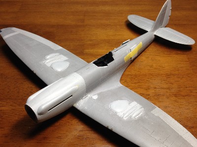 Finally, the wing and fuselage was glued together. |
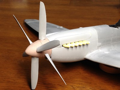 Propeller blades were fixed on 4mm (0.16") holes. |
|
|
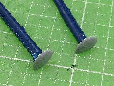
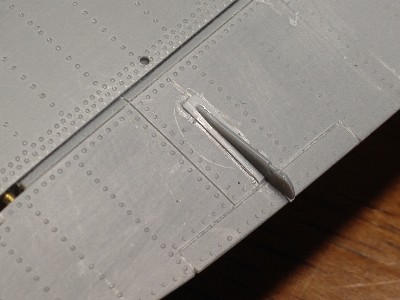
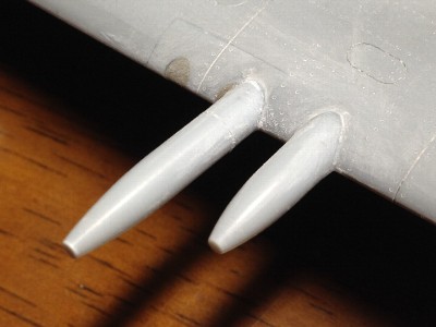 The cannon barrel sleeve were made of 4mm styrene rod with rotary tool. |
 The base of arrester hook was made of styrene sheet. |
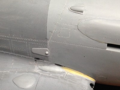 The blister on the starboard filet was defferent from the Mk.XVI. |
 The tab rod had cut from the kit elevator. |
 This is the blister of the aileron tab. |
 The roll bar is the kit part. |
|
|