Zero 52 article part 3
|
|
|
|
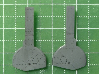
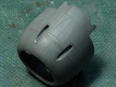
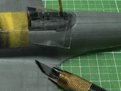
 These are original kit parts of which edges are not so very crisp. |
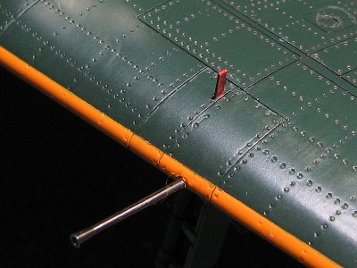
 I engraved this tear drop shaped access hatch with the custom-made template. But the location and size on the kit part is inaccurate. So I had to do it again. This photo shows how it looked before correction. |
|
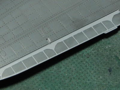
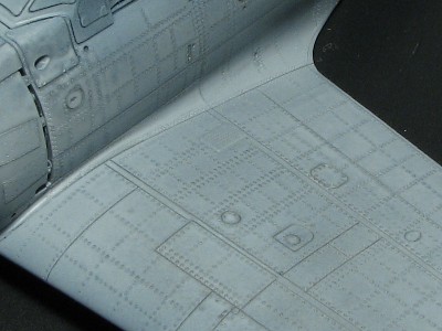
There are two variations of the rivet pattern found on the gear cover. The radial pattern is popular, but horizontal and parallel pattern is confirmed in a photo of captured model 52. However I couldn't find this horizontal pattern in original documentary photos in WWII. |
 The rivet lines location were determined by studying the period photographs. I used #0 beading tool. |
 After riveting, the backside was shaved with a hobby chisel. The original kit is on the right. |
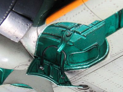
 This small part which connects the cover and leg is main point of landing gear detail work. It is made from 0.3mm and 0.14mm plastic sheet. |
 The edge is sharpened and demarcation line between upper and lower cover is carefully engraved. |
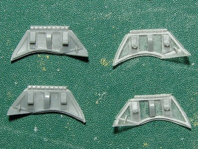
 The cover is finished. Original kit is on the right. I have not worked on the gear leg and tire yet. |
 The upper small cover is engraved with PE saw and hobby chisel. Original kit is on the right. |
|
The fringe of lower cover is bent. This is confirmed by photos of both model 21 and 52 actual aircraft. But I found some photos in which it does not look Åg bent". IÅfm not sure if it was actually flat or it is only photographic effect. |
|
|
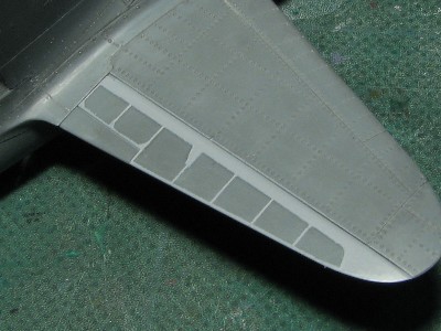
 I added the forgotten center line rivets. |
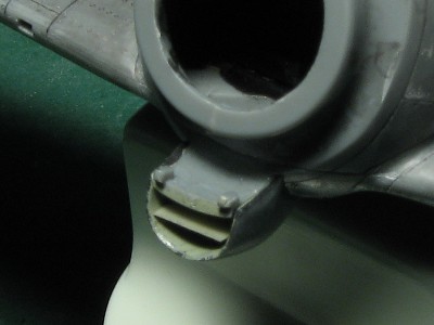
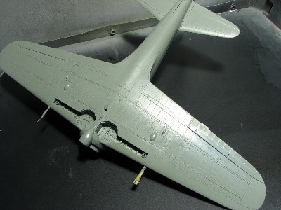
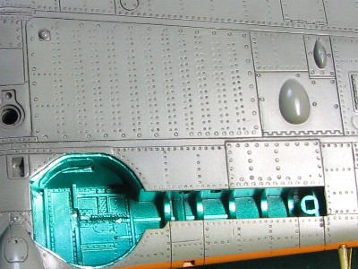
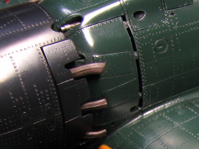
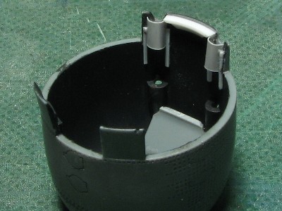 Details are added to the inside. The lowest cowl flaps are cut from the kit oil cooler intake and glued to cowling. Additional benefit is easier painting as well. |
 Details are added to the backside as well and they are not so accurate. |
 They can hardly be seen. It's more for my personal satisfaction and ego. |
|
|
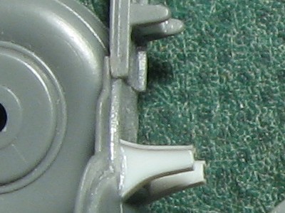
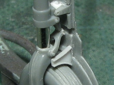
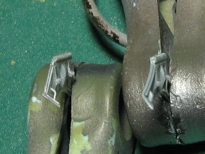
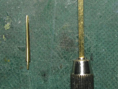
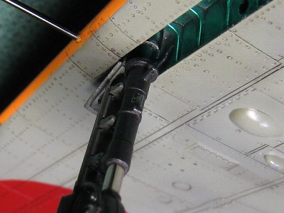
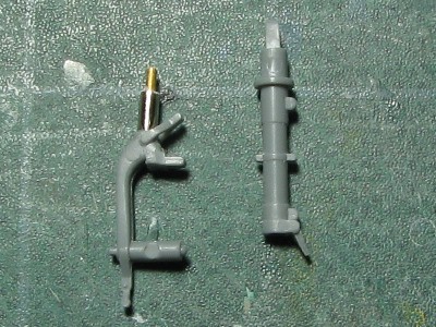 The gear leg is cut at this point shown here. The oleo was replaced by 1.5mm tube. |
 The upper and lower torque links are carved out with a knife and pinvise. The slit between oleo and torque link is the appeal point. |
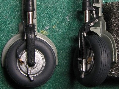
Judging from the period pictures it seems that model 52 had two types of tire-treaded and untreaded. |
 The treads-6 of them- were engraved with etched saw held with a book. The tread spacing was controlled by the number of pages. |
|
In addition, the welding line is represented by stretched sprue, the small piece of plastic sheet is glued on the tie-down ring and the hole was drilled out. |
 The gear is finished. The original kit is on the right. The position of the cover is adjusted to be closer to the tire as a result of sanding the contact surfaces of the tire and cover. |
 This is the close-up. Pins on the hinge are from stretched sprue. 2 or 3 mm pieces were cut and glued on the drilled hole, then cut to proper size. |
|
|
 I fixed the inaccurate rivet lines. I filled them with black super glue and engraved eleven double lines. The new rivets are seen in lighter color. |
 The lower side of trailing edge was carved out to accept the aileron tab. |
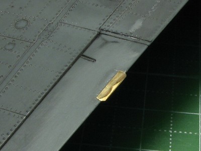 The thin brass plate was glued using CA glue. |
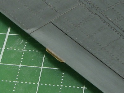 It's finished. This is the upper side. |
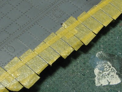
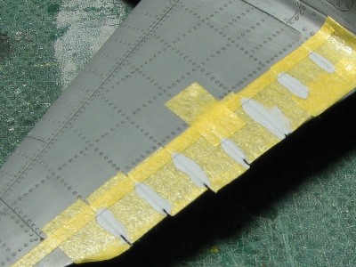
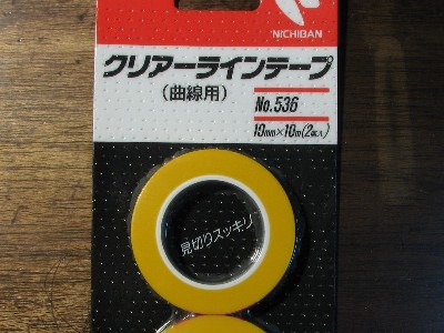 This is Nichiban Clear line Tape. It's very useful as a guide for riveting. |
|
|
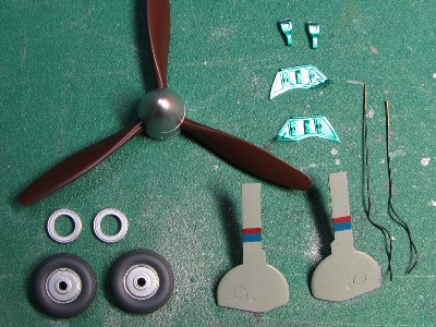
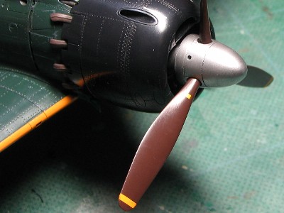
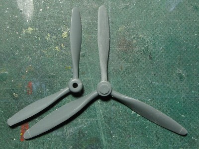 The original parts are on the left, parts from Tamiya Mosquito on the right. |
 The original kit parts are on the top. The center show the actual aircraft pattern. The corrected blade is on the bottom and will be adjusted later. |
|
|
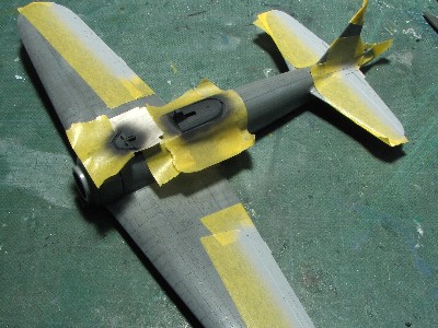
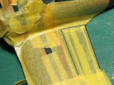
 These are masking tapes for representation of the aileron rib tapes using Mr.Surfacer. |
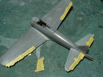 The elevator and rudder were also masked. |
 Thick surfacer was applied in 2-3 layers by brush. |
 Next day, completely dried surfacer was sanded to the thickness of masking tapes. |
 Then tapes were removed. |
 Next step, the fringe was represented. |
 The elevator and rudder were masked as well. |
 This time surfacer was airbrushed to maintain constant thickness. |
 The edges of surfacer were sanded with 800 grit sand paper. |
 Here is elevator. |
|
|
 The inside is sanded. The original parts are on the right. |
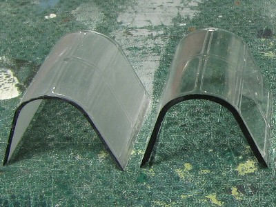
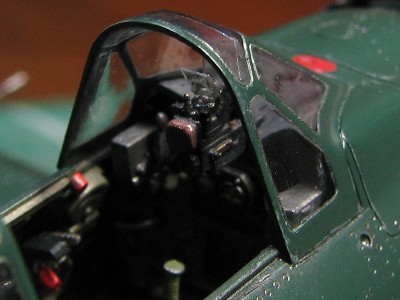
 The wind shield and the fixed canopy were sanded as well. |
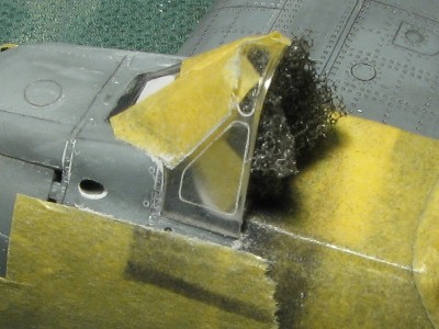
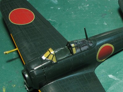
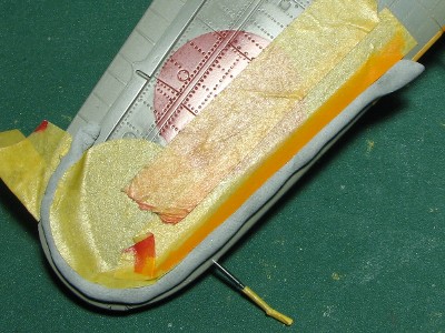
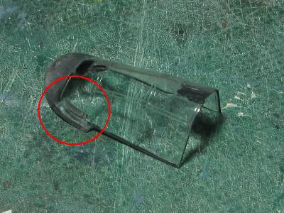 I used thin liquid cement for gluing the canopy clear parts. However the cement got onto the glass portion (see the red circle)! |
 I removed the canopy and cut fuselage for clearance. |
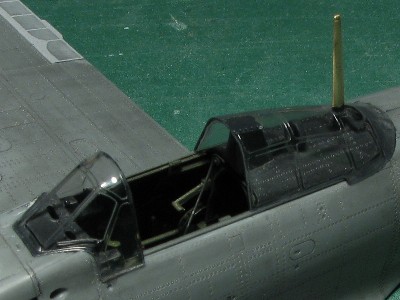 All clear parts have been glued on. Windshield fit was not so good by my experience. It leaned to the back. Was it a kit design or my failure? Anyway, I adjusted windshield and fuselage adhesive portions. |
 I leveled off the glass and fuselage. |
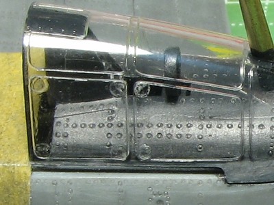 The left window is masked. The right window is being worked on. Small circles were punched out of Scotch tape. |
 Then scotch tape were attached to the canopy and cut with a design knife along engraved lines. Small circle are the guides for cutting corners. |
|
|
 The kit part is on the left. The scratchbuilt part is on the right. The main plate is from 0.2mm plastic sheet, the fringe from 0.14mm sheet, bases of linkage and center wood block were cut from the kit part. |
 The kit part is bent however this is not shown on the actual aircraft. |
|
|
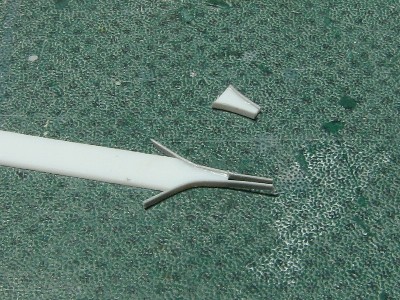
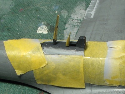
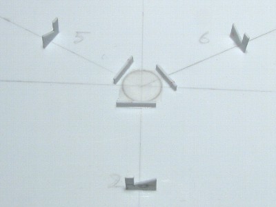
 The antenna mast was made out of the brass rod. |
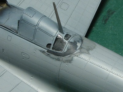
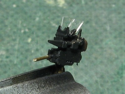 Type 98 gunsight is from Finemold's lost wax brass part. The reflectors are made out of Evergreen 0.13mm clear plastic sheet. |
 The small plate in oil cooler intake was replaced by 0.2mm plastic sheet. |
 I calculated the length of machine gun and pitot tube from actual aircraft photos. Then the 20 mm gun is 9.0 or 9.5mm and the pitot tube is 11mm. |
|
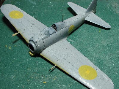
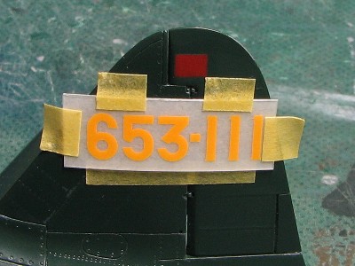
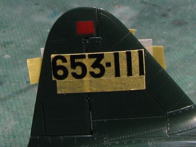
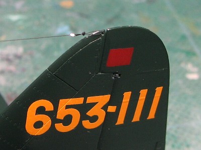
Some sources show the aircraft number 653-111 as white and others yellow. Another aircraft which belonged to 653 kokutai (Mitsubishi built 52-otsu : ref-20) seemed to have it in yellow. So I decided that my -111 will be yellow as well. If the aircraft number was yellow, the small rectangle upper number seemed red. It corresponds to red of national insignia (hinomaru) in the monochrome photo.
|
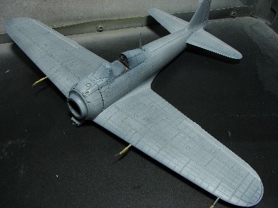 I airbrushed very thin coat of Mr.Surfacer. The purpose of this work is primarily to determine any defects of the surface which are consequently corrected by additional airbrushing. |
 This is the close up. |
 I corrected the gap between the canopy and fuselage. |
|
Please check this site. This Nakajima light green gray was a mix of #128 IJA green gray, #56 Nakajima light green gray and #355 medium sea gray in the ratio 4:3:3. The cowling of Mitsubishi Zero was said to be blue gray. I don't know what Nakajima's was. I guess it was painted simple black. Then I went with a mix of black and white in the ratio 8:2. |
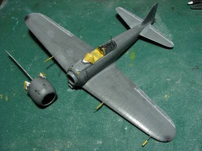
 Under surface is finished. |
 After painting the cowling was polished with Mr. Laplos #6000. |
|
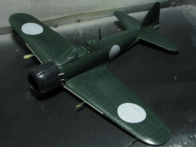
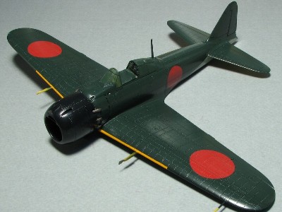
Having studied many WW2 original color photos of various aircraft such as Zero(Mitsubishi), Raiden, Suisei, Seiran, etc. I'm convinced that dark green of IJN and IJA aircraft was rather more bluish and darker than general hobby paints (for example Mr. color #15 dark green). Therefore I mixed IJN dark green from #15 Nakajima IJN dark green, #326 FS15044 (Thunderbirds blue), Gaianotes color #212 green in the ratio 4:4:3 and added 5% of white. |
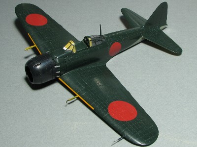
 Hinomaru red and IFF band orange yellow were not painted "on" dark green but painted "side by side" with green. The benefit of "side by side" technique is avoiding the Ågpaint stepsÅh and achieving more even surfaces showing the rivet patterns better. |
 What nation is this? |
|
Hinomaru red was a mix of #GX3 red, #114 RLM23, #15 dark green in a ratio 75:20:5. Orange yellow was #58 orange yellow with a few drops of red. |
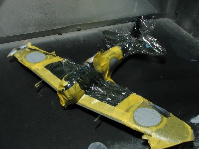 The model is masked with masking tape and kitchen wrap. |
 I had thought that basic painting was finished, but.... |
|
Polishing of the airbrushed surface is a very important step in the whole process. The surface after airbrushing would be "orange peel". I polished the surface every time after each coat of paint was airbrushed with Mr. Laplos #6000 ( same as 1500 ? 2000 grit sandpaper).
|
 The original dark green coat was left as the over painted fringe of hinomaru. |
 The color balance was improved even though it may not be clear in this picture. |
|
I was not satisfied with red color of Hinomarus either. I mixed a new shade from #GX3 red adding a small quantity of #GX5 blue. Thus, this new red shade is more bluish and darker than the original one. |
 |
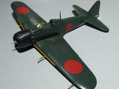 Please compare with the photo above. |
 The "Blu-tac" was used for the color demarcation line on the fuselage sides. |
|
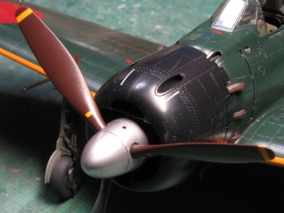
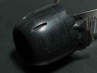
Actually, the spinners were manufactured by Sumitomo company. Thus, the shape or details did not change according to the aircraft manufacturer (Mitsubishi / Nakajima) or model but according to the period of manufacture. The late large spinners appeared in the middle of 1944 and it were seen on some Nakajima built model 52. |
 From the left to right, Hasegawa 52-hei, Hasegawa 52, Tamiya 52 (after correction), Tamiya 52, Tamiya 52-kou. How many variations were there on the actual aircraft? |
|
Tamiya 52 spinner is resembles the actual model 52 spinner most. But comparing to actual photo, the front tip is a little round so I sanded it as per above photo (the center). The actual data of model 52 and 52-kow spinners are listed in Mr.WatanabeÅfs article published in Model Graphic Magazine April 2001 issue. This 52 spinner is the same as "middle type" of this article and 52-kow is the same as "late large type". Tamiya 52 is just equal to this actual data of middle type in the rear end diameter. But itÅfs longer by 1mm. As for the late large type, the rear end diameter is just same as the largest Hasegawa 52-hei spinner, but the Hasegawa 52-hei spinner is too long. Hasegawa 52 has the correct length of the late large type spinner and also the overall shape is accurate however the rear end diameter is smaller. Tamiya 52-kou spinner shape does not correspond to neither middle nor large type due to the rounded tip. On my model I used Tamiya 52 as a middle type spinner without correcting the length. When you build 52-kou model I recommend you use parts from Hasegawa Saiun (Myrt) kit as it corresponds best to the late large type spinner. The length and diameter are almost spot on and the overall shape is good. The front tip is little too pointed so you may want round it off a bit. Considering the above facts the actual Saiun's spinner might be completely identical to the late Zero's spinner. Å@
|
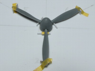
 This is the jig to install the propeller blades. |
 |
|
|
 The panel on the side wall is made of 0.14mm plastic sheet. |
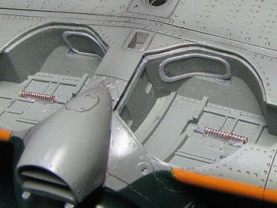 The spring of cover link is made of guitar string (5th for electric guitar). |
|
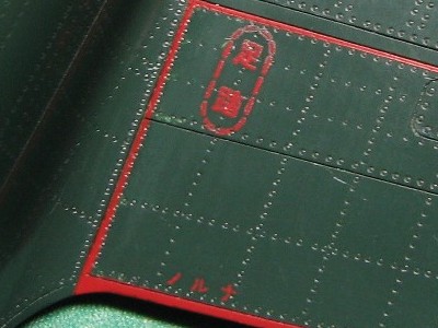
The load indicator on the gear cover of "653-111" was in colors-blue and red. It is confirmed by actual photo. The blue was a mix of #GX5 blue and #335 medium sea gray 50:50. It seems that early 52 model (21, 32, 22 as well) had two color indicator and late 52 model had three colors- red, blue and red. |
 The wheel well is painted in "aotake". Please note the rivets on the wing fuel tank. |
 Detail painting was finished. |
|
|
 I practiced first on Hasegawa Zero kit. The silk sheet (blue gray) was fixed with tape, ink was put beside the printing portion and then ink was printed on the model with the squeegee. |
 I found this technique rather difficult. I think I need to practice more. |
|
|
 The location of the dry decal is determined using the tape located just underside of proper markings. Then the paraffin paper will be removed and dry decal will be transferred. |
 The location is carefully determined not to overlap the hinge line. |
|
|
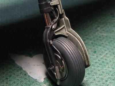
 The brake line is made of annealed 0.3mm brass rod and 0.5mm brass tube. |
 The wheel cover actuator link is made of 0.35mm brass rod. |
 The caution data plate was noticed in this location on Nakajima built model 52. I used the kit decal. The shape, size and location are different on Mitsubishi-built aircraft. |
|
|
 The antenna line was fixed through the hole on the top of vertical stabilizer as on the real aircraft. |
|
|
 |
|
|
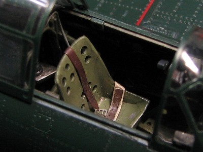
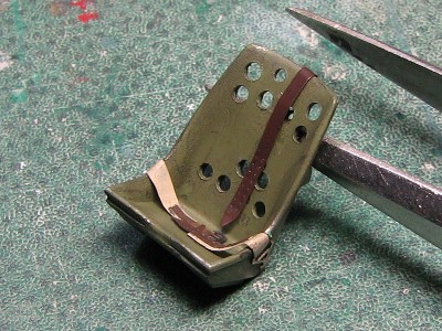 I used the seat from the kit. The seat belts are Finemolds photo etched parts. |
 |
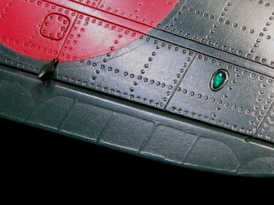 The navigation lights are from Hasegawa P-40. Please note the depiction of rib tapes. . |
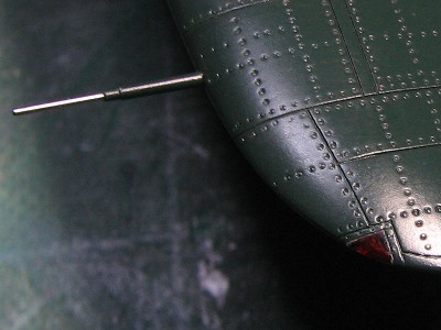 The pitot tube is from Tamiya original metal parts. |
 The 20mm guns are also Tamiya original metal parts. |
 The 7.7mm gun and exhaust pipes. |
 Type 98 gunsight. |
 The brake line is made of 0.3mm brass. |
 These yellow markings are dry decals. |
Most of Nakajima built 52 model had this type of thin white line. These lines are dry transfers. |
|
Tamiya kit is an excellent one. IÅfd say that this is the best 1/48 scale kit of all sorts of aircraft especially in accuracy. I would only comment on two points. One is to rise up wing tip and the other is not to use kit's 52-kou spinner but to exchange it for Hasegawa Saiun's one.
|
| 1 | The famous aircraft in the world No.5 Type Zero Carrier Fighter Model 11-21 (new edition) | Bubrindo |
| 2 | The famous aircraft in the world No.9 Type Zero Carrier Fighter Model 22-63 | Bubrindo |
| 3 | The famous aircraft in the world No.55 Type Zero Carrier Fighter Model 11-21 | Bubrindo |
| 4 | The famous aircraft in the world No.56 Type Zero Carrier Fighter Model 22-63 | Bubrindo |
| 5 | The famous aircraft in the world (old edition) June,1974 Type Zero Carrier Fighter Model 11-22 | Bubrindo |
| 6 | The famous aircraft in the world (old edition) October 1974 Type Zero Carrier Fighter Model 52-63 | Bubrindo |
| 7 | Koku-fun illustrated No.42 Color & Markings of Japan Army and Navy Aircraft | Bubrindo |
| 8 | Koku-fun illustrated No.53 Type Zero Carrier Fighter | Bubrindo |
| 9 | Koku-fun illustrated No.93 Veterans | Bubrindo |
| 10 | Koku-fun illustrated No.96 Photo History IJN 302 Kokutai | Bubrindo |
| 11 | Koku-fun illustrated No.109 Umiwashi to tomoni (With the sea eagles) | Bubrindo |
| 12 | Koku-fun August 2008 | Bubrindo |
| 13 | Model Art separate volume No.272 Paintings & Markings of IJN Fighter | Model Art |
| 14 | Model Art separate volume No.323 Type Zero Carrier Fighter Model 11/21 | Model Art |
| 15 | Model Art separate volume No.378 Pearl Harbor Attack Unit | Model Art |
| 16 | Model Art separate volume No.510 Paintings & Markings of IJN Fighter (new edition) | Model Art |
| 17 | Model Art separate volume No.518 Type Zero Carrier Fighter Modeling Guide | Model Art |
| 18 | Aero-detail 7 Mitsubishi Type Zero Carrier Fighter | Dainippon-kaiga |
| 19 | Battlefield Photo Album of IJN Kokutai | Dainippon-kaiga |
| 20 | Fighting Zero | Bungei-shunju |
| 21 | Photo album of Japan Military Aircraft | Kojinsha |
| 22 | Mechanism of Military Aircraft No.5 Zero Fighter | Kojinsha |
| 23 | Photo Album of IJN Aircraft in WWII | Delta-shuppan |
| 24 | A6M ZERO in action Aircraft Number 59 | Squadron/Signal Publications |
| 25 | WARBIRD Legends | MBI Publishing Company |
| 26 | U.S.NAVY FIGHTERS OF WWII | MBI Publishing Company |
| 27 | Existing Zero Fighter Picture Book | Ei-shuppan |
| 28 | DVD Zero 52 High Vision Master | Wack |
| 29 | Indestructible Zero Fighter | Kojinsha |