Zero 52 article part 2
|
|
|
|
 |
 |
|
|
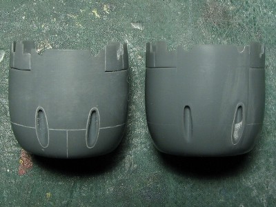
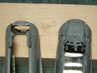 The left is Hasegawa, the right is Tamiya. The widths of both firewalls are the same. |
|
|
| width | height | length | height of opening | width of opening | |
| Tamiya | 25.0 | 26.0 | 22.5 | 16.3 | 15.7 |
| Hasegawa | 24.5 | 25.8 | 22.5 | 15.7 | 15.2 |
|
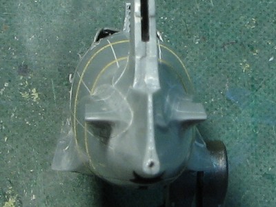
I traced each outline. The red line is actual photo and the blue is the kit. Then I superimposed the images. The two outlines should be identical. Anyhow, we have to consider other conditions such as distortion of the camera lenses and the exact distance from the camera to the aircraft. |
 |
|
|
 |
|
Next, I calculated the error of the tail fin in a photo. The tail fin is located a little farther than the nose. If segment AB is 10m and segment AC is 30m, then BC becomes 31.6m from the Pythagorean theorem (root of 10x10+30X30). Thus, the tail fin is further than nose by 1.6m. The visible size of object is inversely proportional to the distance. So the tail fin looks 5% (30/31.6=0.95) smaller. I'd call it "Error of the distance" in this case. When we think in modeling terms, if the height of the tail fin is 4cm, the error of distance becomes 2mm. It cannot be ignored. Furthermore, the tail fin is seen on a skew by angle ��"theta", then the length appears shorter. Let me calculate this error. The actual length AB looks AE and triangle ABC and ABE is homothetic, so the same calculation leads to 5% error. I'd call it "Error of the angle". In conclusion, the error of tail fin length is the sum of the error of distance and error of angle, 10% total (to be exact 1-(30/31.6)^2=0.90). When we think in modeling terms, if the length of the tail fin is 4cm, the error becomes 4mm. It is too significant! Now let's calculate the total length of the fuselage. I assume that actual length is AB and apparent length is AD. Then, AD=(AC x sin("theta"/2 x 2) , here AC=30m theta=18.4degrees, so AD=9.6m. The error is 4%. If the length of model is 20cm, the error becomes 8mm. Mmmm. Calculations can easily be done using Excel-see below. This table assumes the length of the aircraft is 10m (i.e. AB=10m). When the length is different in your case correct it to proper ratio. |
| AC : distance from camera (m) | 30 | 40 | 50 | 70 | 100 |
| Theta : angle (degrees) | 18 | 14 | 11 | 8 | 6 |
| Error of distance (%) | 5 | 3 | 2 | 1 | 0.5 |
| Error of angle + distance (%) | 10 | 6 | 4 | 2 | 1 |
|
As the result, the error is so large when the distance from camera to aircraft is 30m. Notice that the most of side view photos were taken closer than 30m. At the 50m distance the error decreases and is not a serious problem (1 or 2 mm in 1:48 scale). From 100m the error is ignorable in human eyes. Remember these errors when you look at actual photos.
|
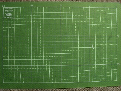 I shot my cutting mat with my camera without zoom. The width of the mat is 20cm and the distance from the camera is about 25cm. |
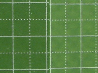 The center and far right of the left photo are combined. The right half shrinks by about 5% in the height and 10% the width. |
|
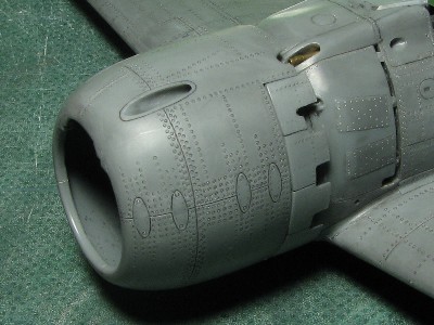
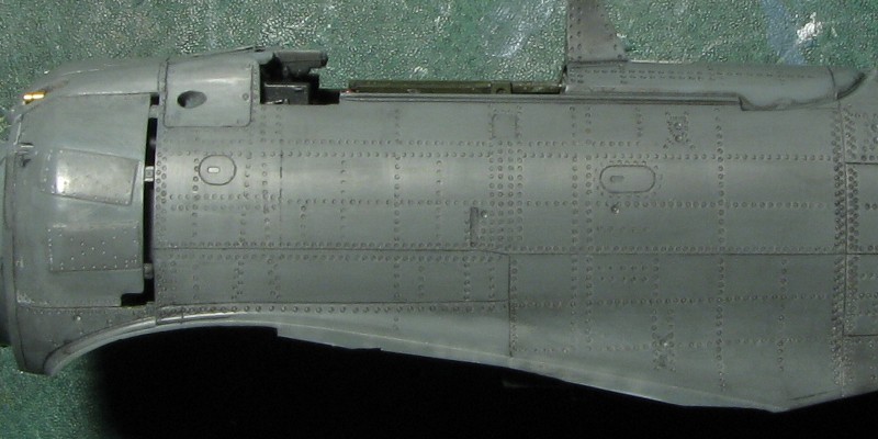
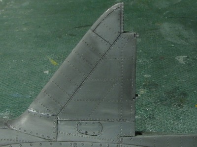
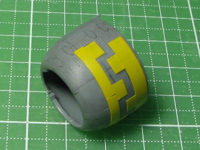
Rearwards of this line a vertical panel line exists near the small square access panel on some models 52 or their later sub-models. If the line is present there are two variants of it - one is located in the center of panel and other is rearwards of the panel as in the picture. I can confirm that this panel line is not found on Nakajima built "standard" model 52 and found on model 52-hei. I cann't establish the exact rule but I suspect the pattern that early production is "without panel line" and late production is "with it". |
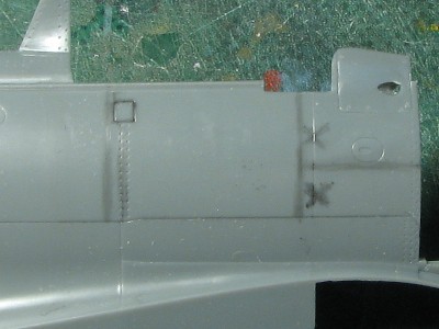 Model 52 doesn't feature the panel line marked �gX�h. So you have to delete it. |
|
|
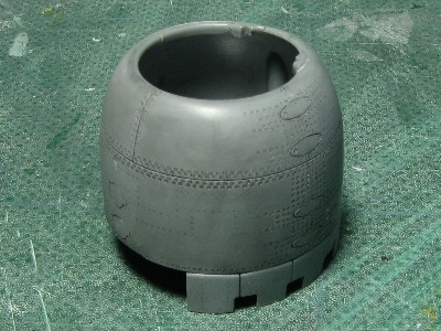
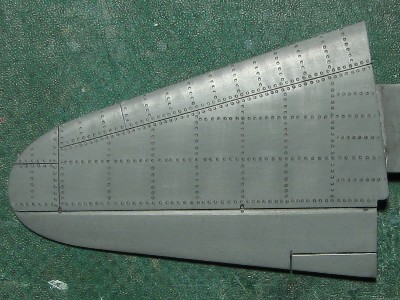
 Rivets have been engraved but the surface is not sanded yet. |
 The oval access hatch was engraved using home-made template. |
|
|
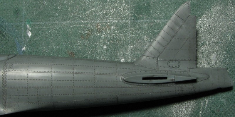 Some rivet lines are still to be applied (will be shown later). The line forward of rudder hinge line is apart from the hinge line at lower end. I mostly used #1 beading tool, #3 on the fringe of the tail fin filet and #0 on the tail cone. |
|
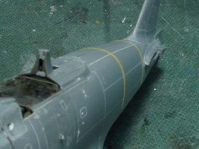
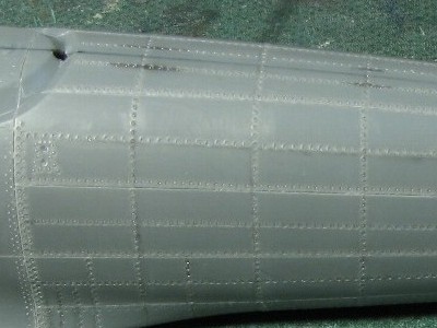
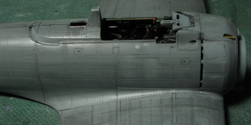
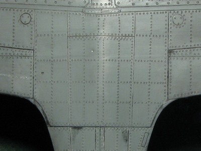
The front half of the fuselage is like this. Basically port and starboard are almost the same but some minor lines are different due to the equipment installation. |
 There are six lines downward of small square panel on the real aircraft but I was unable to represent them in 1:48 scale. There are four lines on my kit then. The horizontal line just above the wing filet was engraved with #2 beading tool because this panel was not a structural one but only for airstream and attached afterwards during the actual manufacturing. Nakajima Zero was riveted with convex rivets. |
|
|
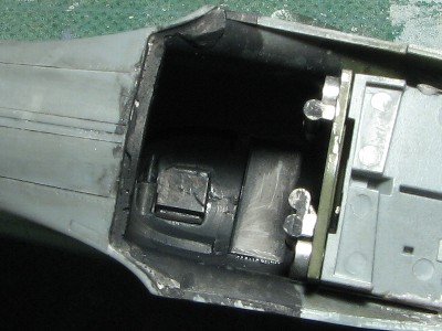 For the purpose of riveting I reinforced the attachment area of the lower wing and fuselage. This reinforcement can be seen through the cockpit even after completion so I painted it black. |
 Then I glued the fuselage and the wing. I used super glue on the front and rear, and used thin liquid cement for upper filet side. |
|
|
 The rivet line which was filled with light gray putty may be found on port side only. The small hole under the windshield is opened on port side as well. Kit filet is too thin and I made holes during riveting process so be careful. |
 Previously left off rivet lines were added at this stage. |
 Underside of the fuselage looks like this. |
|
The integral structure of the fuselage and wing can be understood. In this picture, the horizontal lines are the parts of fuselage frames. Therefore the rivet lines correspond to their locations. The wing rib nr.03 represents the border line of attachment to the fuselage structure. This is the example of Mr. Horikoshi's indigenous design how to balance strength and weight.
|
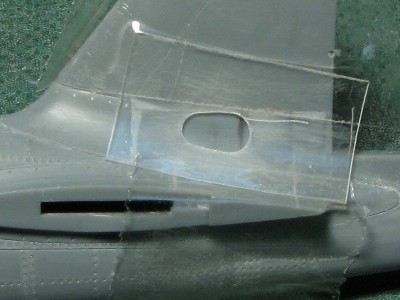
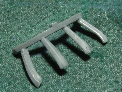
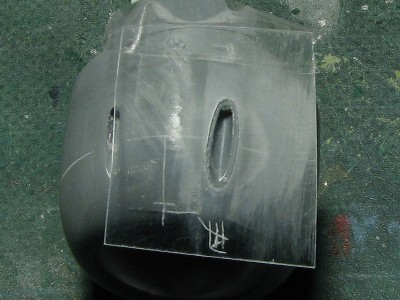 This is a custom-made template from 0.2mm thick plastic sheet. It is fixed with double sided tape and regular scotch tape. |
 |
|
|
 Original kit is on the right (1 degree open). Modified kit is on the left (-2 degrees close). No too much change visible? |
|
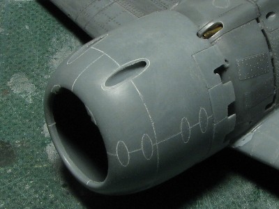
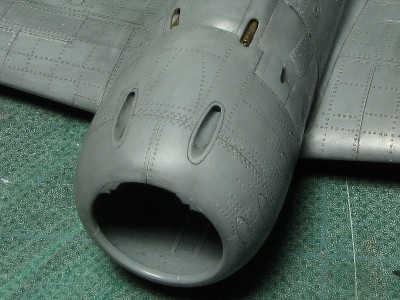
There are some variations found on the existing aircraft. I don't know the origin of these variations. They may have been caused by a model sub-type, period of manufacture, manufacturer or restoration work. Anyway I tried to depict the pattern of Nakajima-built standard model 52. Mainly I used the photos of existing cowling fromf RAF Museum in Cosford (this cowling and engine is said to be from the same aircraft as an IWM Zero fuselage).
The change of the shape of cowling was required due to the airflow of the engine. So if I was an engineer in charge, I would think that the changes on the production line should to be minimized, then the cowl flaps and gun tubes not to be changed and use the maximum of the existing 52 cowling. Thus only the minimal portion of the panel between the two gun tubes would be cut and the new bulged panel just installed..... Well, this is my inference. What do you think?
|
|
Riveting was almost finished. I used #1 beading tool but it's a little over size. |
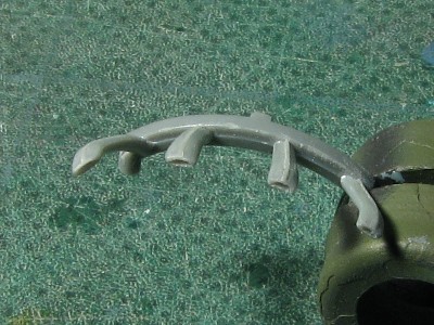
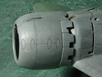 The forward edges of the cowl flaps are not straight but slightly curved. |
 The upper side is like this. |
 Comments are as follows. |
|
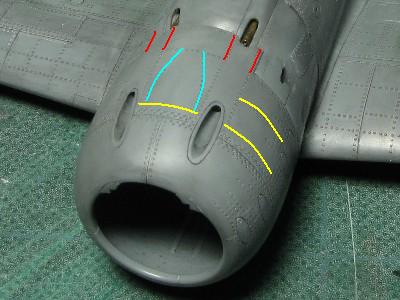
Nakajima built Zero has eight convex rivets at the red line. This is confirmed by POF, cowling from Cosford and the original WWII photo. I don't know about Mitsubishi-built Zero but some restored Mitsubishi aircraft don't have these convex rivets. The blue lines are for fixing of the air duct. This air duct can be confirmed from Cosford cowling etc. Accuracy of the yellow lines is deducted from the inner structure which fills the gap between the engine and cowling. |
 There are double crank shaped lines on the lower half of the cowl. These lines are confirmed by POF aircraft. This shape seems to be created by the inner parts made of canvas to absorb the vibration (reference-27) and each corner corresponds to cylinder heads. |
 This canvas is also put on upper cowling but there is gap and the canvas is put on the inner structure so the crank rivet line does not appear on the cowling surface. |
|
|
 This is the starboard exhaust. The welded line is depicted with a stretched sprue. |
 Pipe ends were drilled out. |
|
As for starboard side, my friend send me photos of Mitsubishi 52 kou which was discovered on Guam islands after the war and the starboard heat proof plates are half size of Nakajima. But these photos only show two upper plates so the lower plates' size remains unknown (but I guess they were the same as the upper ones). It is also said that the early production of Mitsubishi 52 didn't carry those plates at all. Model Art Magazine article stated that starboard plates were larger than Nakajima, but I have my doubts.
|
 |