Zero Fighter model 52 part-1
|
|
Great thanks to Mr. Mario for checking my English text.
|
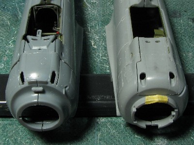
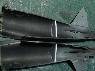
The canopy is the main point of difference between Tamiya and Hasegawa. Tamiya rectified Hasegawa's inaccuracies i.e. canopy is too wide at upper portion resulting in the steep angles of the side windows. Hasegawa canopy is taller than Tamiya by 1mm and that's why Hasegawa fuselage looks slim to some modelers. Both cowlings are slightly different and therefore a matter of personal preference. Tamiya's main wing is excellent. Distinct washout (see this photo) of Zero is perfectly represented and the airfoil is accurate. The airfoils on both kits are a little different therefore it will be difficult to mate Hasegawa "52-hei" wing to Tamiya fuselage and build 52-hei model. |
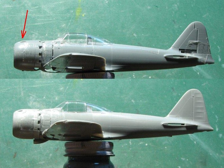 Tamiya is on the top, Hasegawa on the bottom. Especially, the curve at the arrow is different. Hasegawa looks like somewhat cartoonish since it's canopy is large and fuselage is short. |
|
My conlusion is that Tamiya kit is more accurate however Hasegawa kit is remains an excellent choice.
|
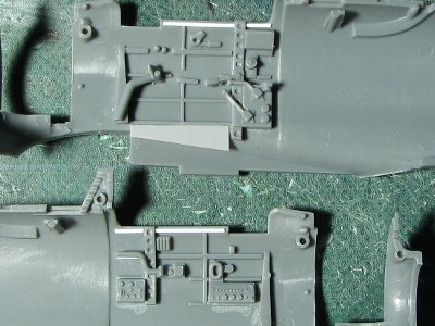 The cockpit upper edge is rather devoid of details so I added Evergreen plastic rod (0.4 x 0.5mm) to represent the stringers. |
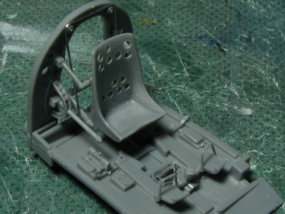 The seat mounting braces were thinned as well as the edges and back of the seat. The seat pulley string was made from 0.3mm solder. Foot holding straps were added to the rudder pedals. |
|
Anyway, I mixed my interior color from Mr.color #303 FS34102 and #127 Nakajima interior in the ratio 3:1 and added small quantity of #22 dark earth.
In addition, model 21 or 32 were also painted dark gray. There is a original color photo of model 32 in ref.-26, the color was faded dark gray, not light gray or interior green.
|
 The gun control box below the instrument panel was painted dark green. It was not black. |
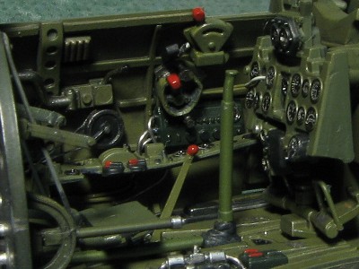
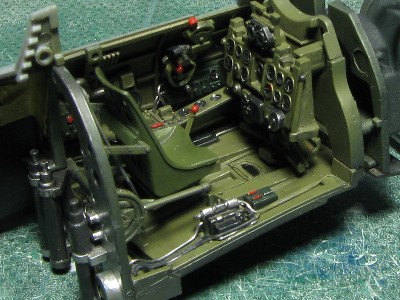 The left side. The seat was painted #340 field green. Instrument were manufactured and painted at subcontractors. All were painted in slightly different shade of green. |
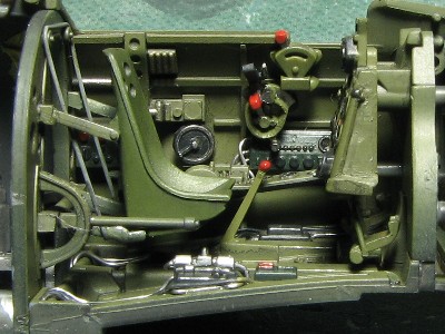 Electrical distribution panel of existing original parts was not black but dark green. Please note the dark silver gun trigger on the front of the throttle lever. |
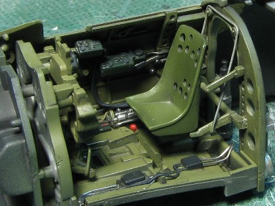 Aaviation radio and Kruesi Radio Direction Finder were dark green. |
|
|
 Tamiya is on the left, Hasegawa on the right. |
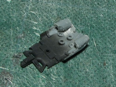 I filled the bottom of the slots with sprue. |
 After I finished I realized it was a waste of time since the job is not visible. |
 I installed bulkheads in the rear fuselage. They were reinforcement and protection of dust. |
|
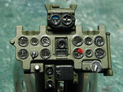
Please notice that IWM Nakajima Zero 52 lacks two instruments and other captured 52 model on Saipan lacked only aviation watch (ref.-16 etc). Two front instruments on the left console were dropped off from both of IWM and Saipan aircraft. |
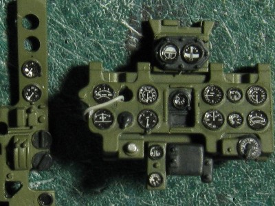 Since I had two full kits I modified the instrument panel. I had no Hasegawa decals left so I used two sets of Tamiya decals. The string was made from 0.2mm lead wire. |
 The cable from the trim handle, the gun selector lever (above the trim handle) and the throttle cables were added. |
|
|
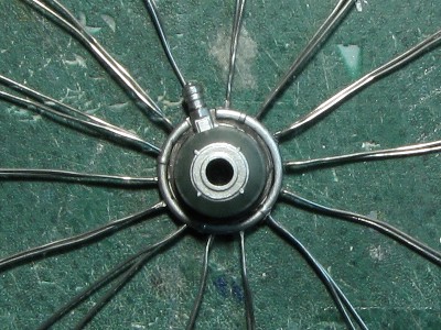 I installed 28 spark plug cables made from 0.3mm solder wire. |
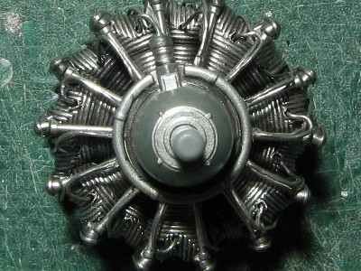 The engine was finished. The late model Zero engine looked unpainted. So I simply used #8 silver + #2 black. |
|
As far as Nakajima built Zero is concerned thing are more complicated. I checked a lot of original photos and judging from brightness I concluded that many aircraft did not have inside of the landing gear covers painted in Aotake (for example, ref.-2 page51, ref.-8 page108, ref-10 page31). I think these were painted light gray (someone say that latest Zero (after 52-hei?) were left unpainted to simplify the manufacturing process but it is not confirmed). On the other hand, some Nakajima Zero's gear cover seemed to be painted Aotake ( for example, Nakajima built 21 and Saipan captured 52) judging from original monochrome photos. The wheel wells and the crescent moon shaped wheel cover of IWM Zero were painted Aotake. (The main landing gear cover of IWM aircraft was painted light gray, but it possibly was taken from Mitsubishi built Zero.) On the other hand, light gray painted wheel wells on Nakajima built Zeros seem to exist. I checked a lot of original photos but I couldn't make any conclusion due to the poor lightning of the gear bay and wheel cover areas. I would conclude that the most of Nakajima built Zero 52 had wheel wells and small wheel cover painted in Aotake and the main landing gear cover in light gray but were some exceptions. There are other variations in painting of the landing gear. There are two types of weight indication at the center of gear cover. One is red/blue and another is red/blue/red (most of color instruction are red/yellow/blue, but existing record shows red/blue/red). Also there are variations in the name plate on the upper gear leg (position / size / with or without), the color of torque link (silver / black). The "U" shaped wheel cover link is made of chrome molybdenum steel and painted black.
|
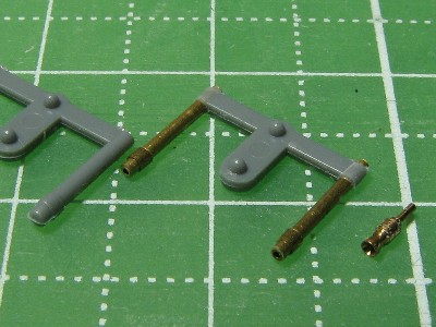 Kit parts is on the left, scratch-built parts in the center and Fine Molds parts on the right. |
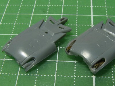 Guns are temporarily installed in the upper fuselage panel. |
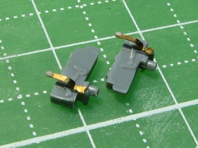 This is the gunstock of 7.7mm gun. The mold of the lever was cut off and PE lever was added. The lever head was made using super glue putty. |
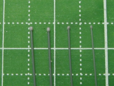 These are the trial pieces of lever heads made from super glue putty. Key point was to adjust the putty viscosity. |
|
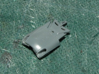
Before gluing fuselage halves, I checked the fit of fuselage and wind shield. The width of wind shield was slightly larger so I inserted the 0.14mm plastic sheet. |
 The reinforcements were installed into adhesive portions. |
 After gluing I lightly sanded the surface. |
|
|
| rib no. | chord | thickness | chord thickness ratio | angle of attack | curvature diameter of leading edge | distance from wing root |
| 01 | 53.9mm | 7.7mm | 14.3% | 2.0�� | ��2.2mm | 2.6mm |
| 12 | 42.4mm | 6.0mm | 14.2% | 2.0�� | ��1.7mm | 51.6mm |
| 21 | 33.4mm | 3.7mm | 11.1% | 1.0�� | ��0.9mm | 90.1mm |
| 26 | 26.5mm | 2.4mm | 9.0% | -0.5�� | ?? | 112.0mm |
|
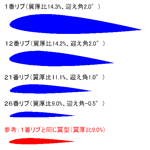
Traced drawings are as follows |
 |
|
The rib-01 is located inside of fuselage. The rib-12 is the border of flap and aileron for model 52. The rib-26 is hinge line of model 21 wing tip. From the root to the middle of wing, chord thickness ratio is almost constant (of course, chord is decreasing so the thickness is decreasing) and the angle of incidence is constant. From the middle to wing tip, thickness markedly decreases and wing tip features the wash-out (twist). That is the feature of a miracle wing that gave Zero its high performance. Please note the curvature diameter of leading edge. The diameters are unexpectedly small (i.e. the leading edge is sharp). Most of modelers neglect this fact. I sometimes saw Zero with Hurricane-like wing leading edges. Tamiya kit well depict this feature. The dihedral of Zero is 5.71 degrees. This value is on the center of wing spar. The maximum thickness is at 30% of the chord.
The airfoil shape of the outer wing changes little by little to drop down to the leading edge. As the result, the lower surface of rib nr. 26 is almost flat (see above figure of blue rib-26 airfoil ; the red airfoil is similarity of rib-01to -12 airfoil). So the leading edge sine curve is noticeable for double effect of twist and airfoil. On the other side, the trailing edge sine curve is only of twist so it isn't noticeable and it looks like as if the trailing edge is bent at the border of flap and aileron when I see photos of actual aircraft. This wash-out is easy to describe in words, but it's not easy to design and build in reality. The cross section shape of four flanges (upper/lower front/rear) are changed in 3D and each change is different. |
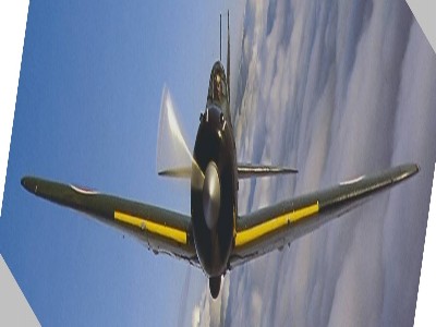 This photo of Planes of Fame's Zero 52 (in ref.-25) shows a width reduction. Notice the highlight of port wing. Also notice the wing tip. |
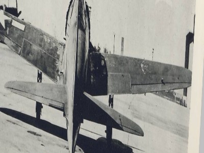 When you use your ruler you'll understand the bend (ref.-6). |
|
|
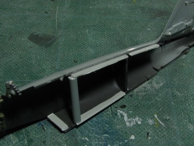
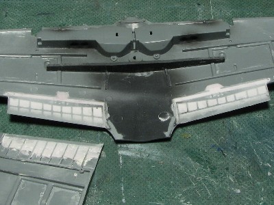 The carbon fiber spar was glued onto the lower wing part to maintain the correct dihedral. The inside of flap and upper panel of flap were filled with super glue putty to reinforce the structure in preparation for riveting. |
 The depressed areas appeared after the surface was sanded. |
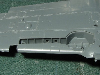 The wall of gear bay was thinned and the holes were drilled out. The location and the size of holes were not completely clear from my references. |
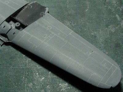 The wing was finished. The wing tip was corrected. I bent upper and lower wing parts by hands and lifted the wing tip up by 1mm. |
|
|
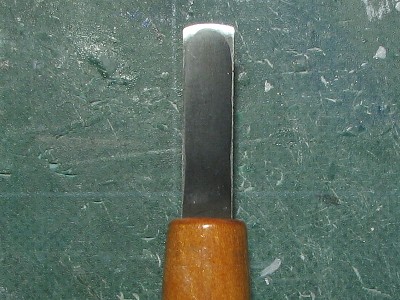 This is the chisel I used. |
|
|
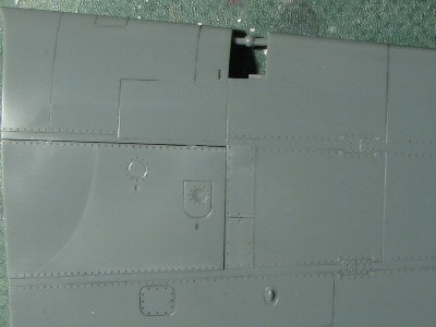
 The location of this hatch was wrong. I filled it with the Black super glue and rescribed. |
|
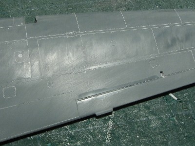
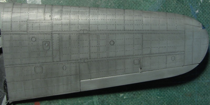
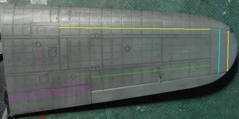
I engraved 12 double-lines of rivets on the lower surface of main wing fuel tank, but later I found out that there were 11 of them, not 12. The photo shows 12 lines, I corrected it later. |
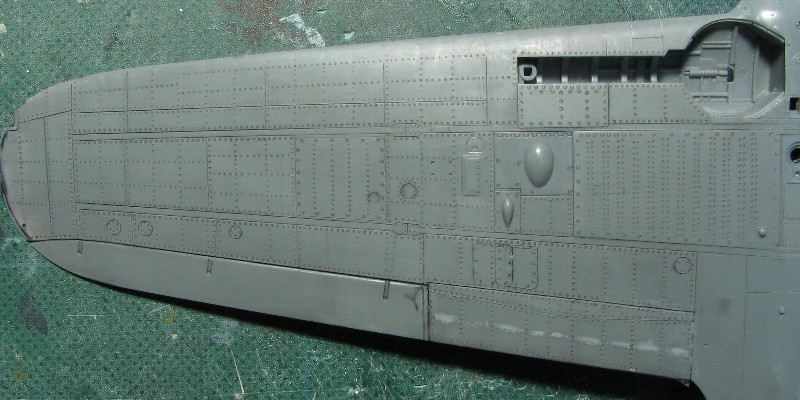 I used #1 (0.3mm) beading tool mainly, #4 for fasteners and #0 for main fuel tank. The gray putty on the flap is correction of my error. I think the rib in this location does exist but was not riveted to the surface panel. |
|
I could see more rivet lines at the upper flap of photos of POF's Zero. But I omitted them because it might look too "crowded" after I have engraved all the rivet lines. |
 I finished the upper wing. To maintain the spacing of the parallel double-rivet lines I used a guide made from plastic sheet. |
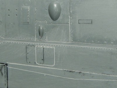
 This is the original kit. Please compare the panel lines. |
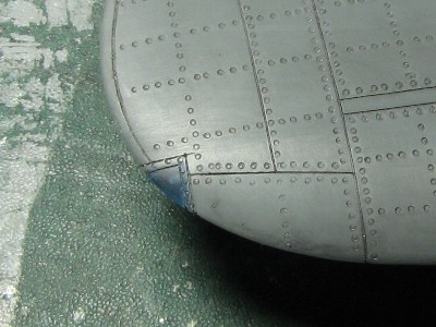 The navigation light was made from colored acrylic material. |
|
|
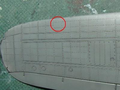 Red circle shows my error caused by inaccurate drawing in ref.-18. The line should be the same as on the upper wing. |
|
|
 |
|
Unfortunately, it was after completion of my Zero, so the seat wasn't used for my model. Instead, I introduce SBS resin seat here. Please check their site. |
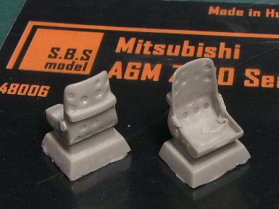 This seat is very good quality. |
|
|
| 1 | The famous aircraft in the world No.5 Type Zero Carrier Fighter Model 11-21 (new edition) | Bubrindo |
| 2 | The famous aircraft in the world No.9 Type Zero Carrier Fighter Model 22-63 | Bubrindo |
| 3 | The famous aircraft in the world No.55 Type Zero Carrier Fighter Model 11-21 | Bubrindo |
| 4 | The famous aircraft in the world No.56 Type Zero Carrier Fighter Model 22-63 | Bubrindo |
| 5 | The famous aircraft in the world (old edition) June,1974 Type Zero Carrier Fighter Model 11-22 | Bubrindo |
| 6 | The famous aircraft in the world (old edition) October 1974 Type Zero Carrier Fighter Model 52-63 | Bubrindo |
| 7 | Koku-fun illustrated No.42 Color & Markings of Japan Army and Navy Aircraft | Bubrindo |
| 8 | Koku-fun illustrated No.53 Type Zero Carrier Fighter | Bubrindo |
| 9 | Koku-fun illustrated No.93 Veterans | Bubrindo |
| 10 | Koku-fun illustrated No.96 Photo History IJN 302 Kokutai | Bubrindo |
| 11 | Koku-fun illustrated No.109 Umiwashi to tomoni (With the sea eagles) | Bubrindo |
| 12 | Koku-fun August 2008 | Bubrindo |
| 13 | Model Art separate volume No.272 Paintings & Markings of IJN Fighter | Model Art |
| 14 | Model Art separate volume No.323 Type Zero Carrier Fighter Model 11/21 | Model Art |
| 15 | Model Art separate volume No.378 Pearl Harbor Attack Unit | Model Art |
| 16 | Model Art separate volume No.510 Paintings & Markings of IJN Fighter (new edition) | Model Art |
| 17 | Model Art separate volume No.518 Type Zero Carrier Fighter Modeling Guide | Model Art |
| 18 | Aero-detail 7 Mitsubishi Type Zero Carrier Fighter | Dainippon-kaiga |
| 19 | Battlefield Photo Album of IJN Kokutai | Dainippon-kaiga |
| 20 | Fighting Zero | Bungei-shunju |
| 21 | Photo album of Japan Military Aircraft | Kojinsha |
| 22 | Mechanism of Military Aircraft No.5 Zero Fighter | Kojinsha |
| 23 | Photo Album of IJN Aircraft in WWII | Delta-shuppan |
| 24 | A6M ZERO in action Aircraft Number 59 | Squadron/Signal Publications |
| 25 | WARBIRD Legends | MBI Publishing Company |
| 26 | U.S.NAVY FIGHTERS OF WWII | MBI Publishing Company |
| 27 | Existing Zero Fighter Picture Book | Ei-shuppan |
| 28 | DVD Zero 52 High Vision Master | Wack |
| 29 | Indestructible Zero Fighter | Kojinsha |