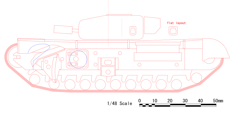
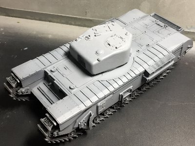
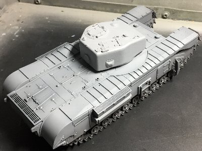
Infantry Tank Churchill AVRE Mk.IV Tamiya 1/48
|
|
|
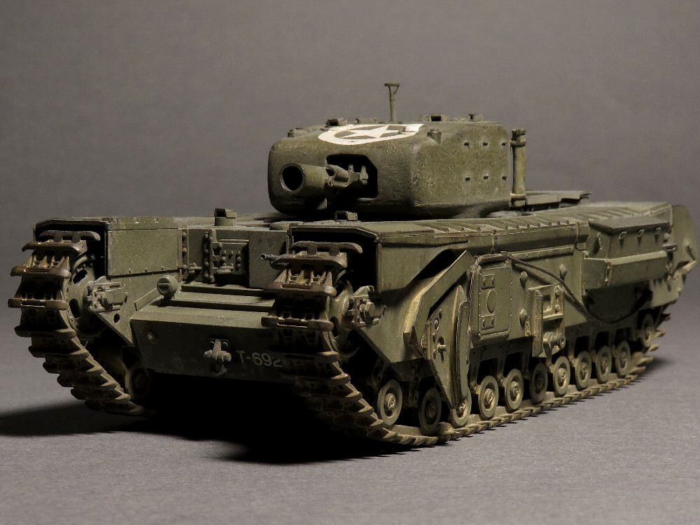
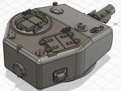
The portion that connected to the circular cross section of the underside and the turret side was a bit different from the actual turret, because it couldn't be reproduced with my design skills. But it is easy to fix with putty, so there is no problem in practical use. By the way, while I was designing, I referred the 1/35 kit on the web. I found that some of the kits did not correct in the basic turret shape. Its front part is too flat. As for the mortar, the accuracy was not so high in dimention, because it was determined from a slightly oblique photograph. If you are worried, use the Scale command to make it just the right size. |
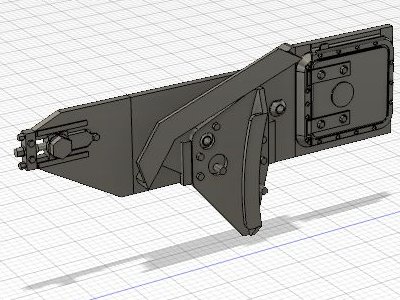
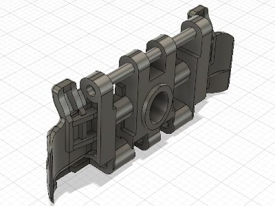
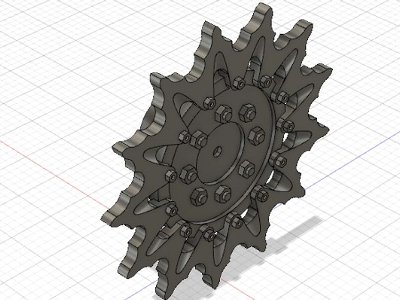
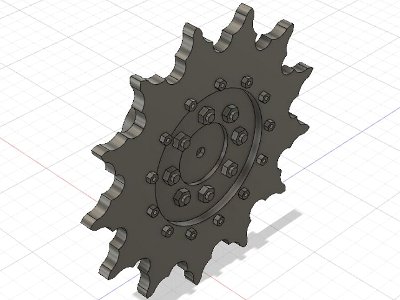
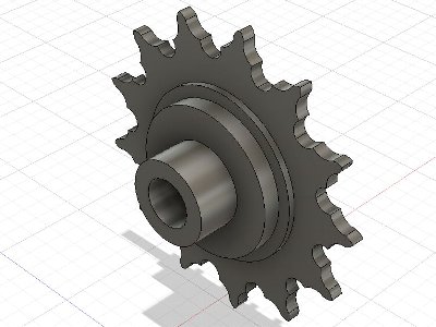
 Sketches were extruded and intersected. After this, chamfer it with a Fillet and cut out the inside with shell to 1mm thickness. |
 I feel that the impression of the printed product is better when the design is slightly emphasized. The hatch groove is 0.35mm wide and 0.5mm deep in design. But it became narrow and sharrow in the print. |
 Differences of variation can be changed retroactively in the timeline. |
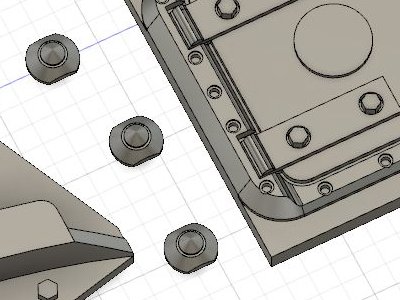
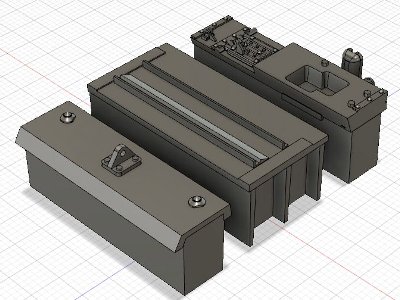
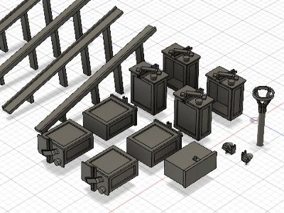
 The luggage box would be kit part. |
|
|
 |
|
|
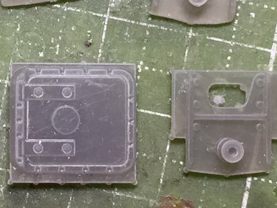
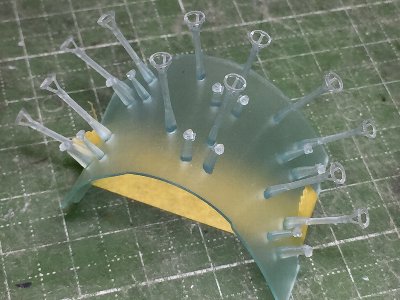
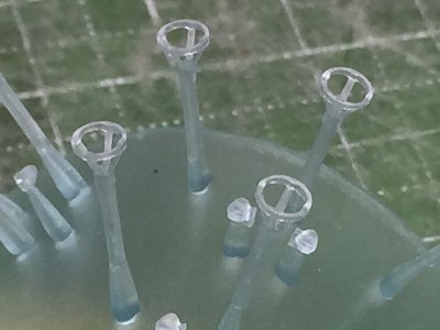
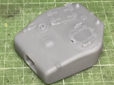 Theis is the first trial print. The layer thickness is 0.05mm, exposure time is 10 second. |
 Both mortars were printed in upright (The muzzle was top in a slicer, bottom in a printer.) |
|
|
 |
|
|
|
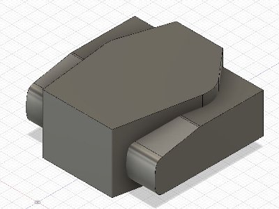
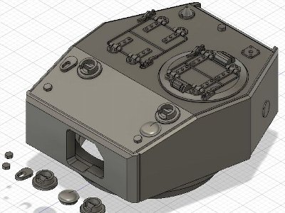
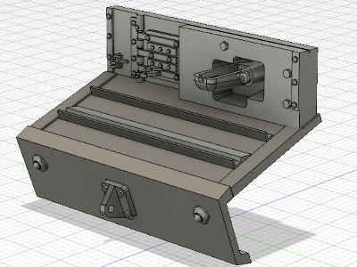
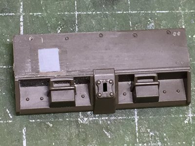
The side of the hull was designed integrally with the side armor plate. However, thin plate-shaped parts often curve when printed. Therefore, the hatche and attachments were designed to be printed separately for each part. There are variations on the hull side as well as the turret. Many vehicles have additional armor plates on the sides. This is also cool, but there is concern about the above-mentioned curving problem. So I designed without additional armor. There are variations on the shape of the bolt on the attachment as well. |
 In the final design, the side armor plate is included. But each hatch and attachment can be printed separately. |
 Close-up of the hatch. It is easy to design, such as a dent around the bolt, but it is not reproduced when printed. |
|
|
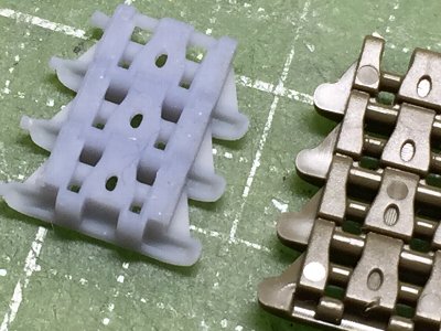
 The result is good enough for practical use. With such a small size, the curvature is hardly noticeable. |
|
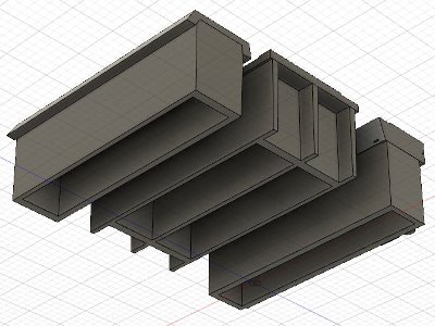
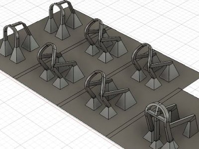
Output was troublesome. Due to the fate of LCD printers, it is difficult to print a large size plane as a perfect plane. The reason is that a large flat part curves when fully cured. Therefore, reinforcement frames as shown in the image below were attached and cut off after curing. This frame resisted internal stresses that would curve. |
 Basic 3D design work is finished. |
 In order to prevent the occurrence of lamination marks, each plane is placed on the upper side in printing. Reinforcement frames need this height. |
 The back side looks like this. If the ceiling is slightly inclined by "moving the surface" (← fusion360 terminology), support is unnecessary. |
 Parts are printed, cut off unnecessary parts and lightly sanded. |
|
As you progress the timeline through the end in Fusion360, reinforced walls will appear.
|
 Design work was finished. Pins for supports were designed. |
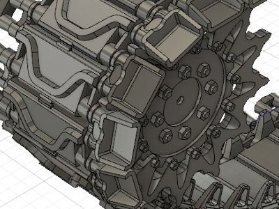
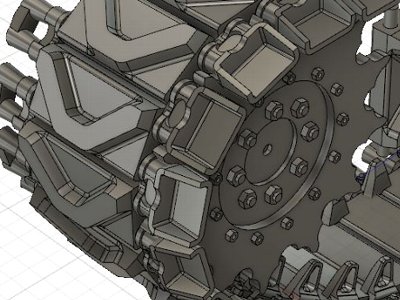
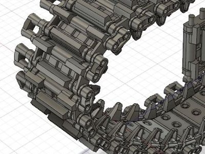
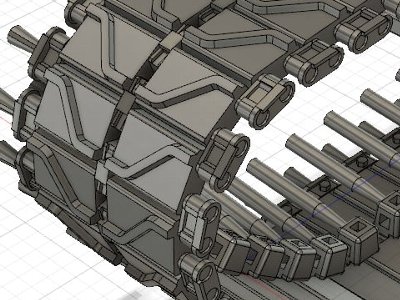
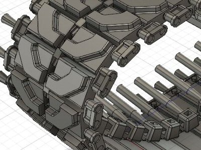
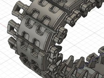
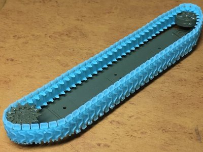
 This is the back side. The point is the dent on the back side of the tread. The thickness of the parts is designed at 0.3mm. Also pay attention to the differences in the parts where the wheels ride. Right and left side parallel is correct. |
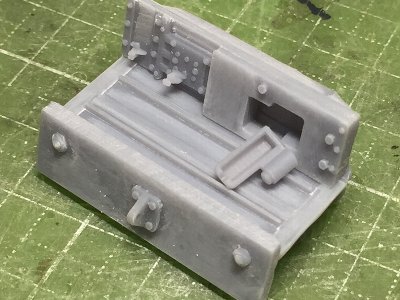
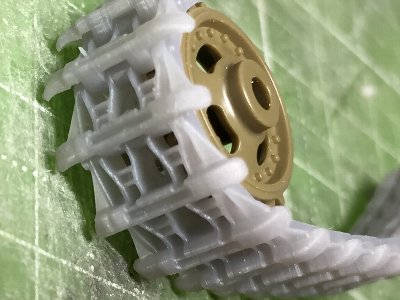 This is a printed state. The depth of the detail carving is the point of discrimination from the kit. |
 The dent on the back side feels good. The kit is not reproduced at all. The central hole is not open either. |
|
|
 |
|
|
 |
 |
|
|
 This elasticity is great. The antenna base itself is perfectly strong. At the time of output, the bottom plate is flat. |
 Closing up of the left image. |
|
|
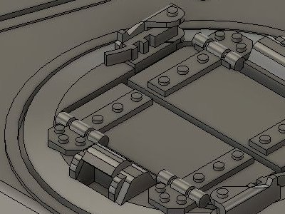
 The 3D parts were designed as just size. So, the protruding parts of the kit were cut off. |
 The kit outside telephone were cut off because MK.IV is different from VII as for the position and shape. The phone would be 3D printed later. |
 The 3D parts was carefully positioned and glued with CA. |
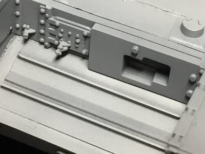
 The hull top and turret were temporarily assembled. The periscope and ventilator arrangement in front of the driver's hatch is different, so this portion was cut out and replaced with plastic sheet. |
|
|
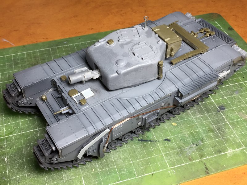
 The backside of the 3D printed parts was sanded to be flat. Thin liquid cement is used for a wide adhesive surface. The hull side parts are not yet glued to the hull top. |
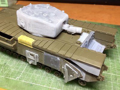 The hull top and turret were tentatively combined. |
|
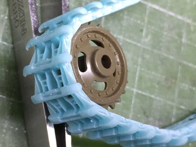
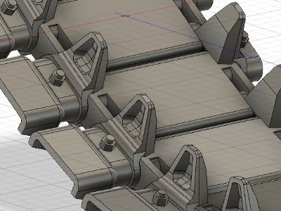
The next problem was that the yield rate was still extremely low. The phenomenon that the upper part was not output from a certain layer frequently occurred. This is a digital bug, so if this happened, I had to start over from works with a slicer. Also, it seems intuitive, the appearance frequency was high when the data of the STL file was large. The third problem was that the idler wheels did not fit well on the printed tracks. The distance between the inner and outer holes was slightly shorter than the kit track. However, if the distance was expanded to match the kit idler, the road wheels did not fit. As a countermeasure, the adhesive part of the idler wheel parts was sanded to narrower the width. |
|
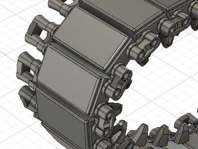
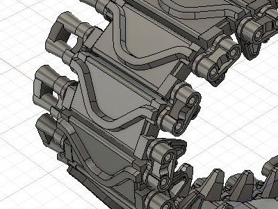
This is the first test print. There is a crank-shaped step on the left side as viewed. This is where the track's side plane emerges just here. |
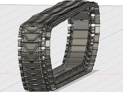
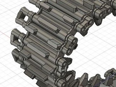
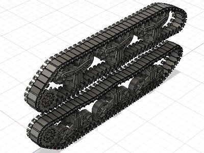
 This is a final print. After hardship, it was finally adopted. Tracks were printed in three parts: front, bottom, back. |
 The adhesive portion of the idler wheel and the drive sprocket were sanded by about 0.5 mm. |
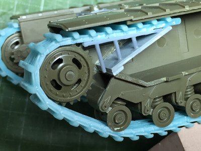 Assemble of tracks to the hull was completed. Rails (gray) somehow did not fit in size (a design mistake?). Then they were cut to fit. |
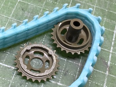
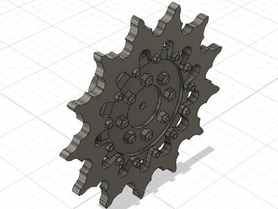
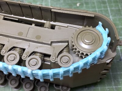 As expected, the drive sprocket did not fit the shaft. Therefore, the shaft was cut and drive sprocket was assembled. After that, 3D tracks data was revised to fit. |
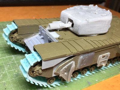 The top and sides of the hull were glued together. Then the basic assemble was finished. |
|
|
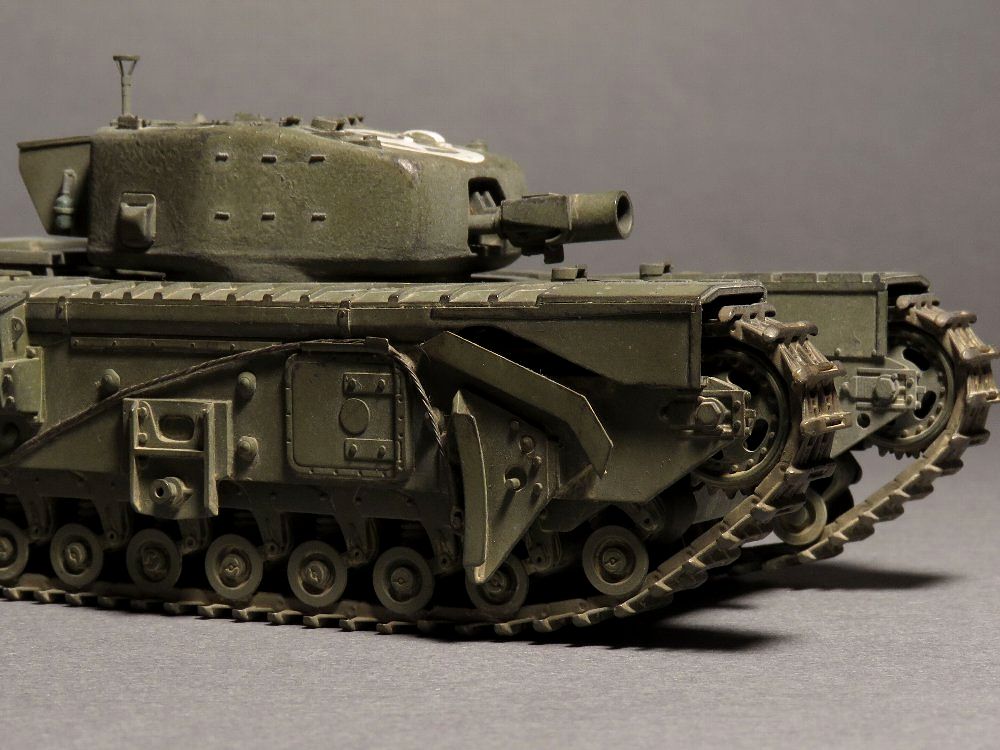
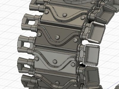
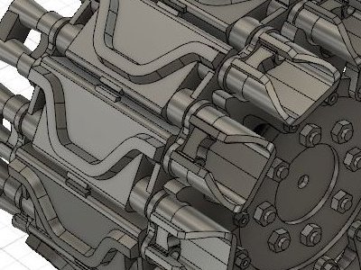
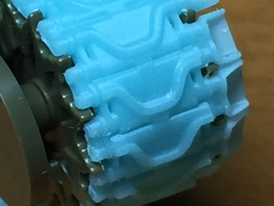
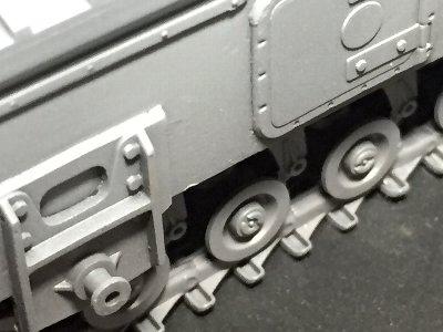 Note the reproducibility of the details, especially the dent inside the tracks. Bolts have adhered to the side wall. Although separated in the data, it was caused by the "magnification" phenomenon inherent in LCD printers. |
 The reproducibility of the details on the front of the hull is good enough. The reproducibility of the horizontal groove of the driver's hatch is low. Later, the data was revisited. |
 |
 |
|
|
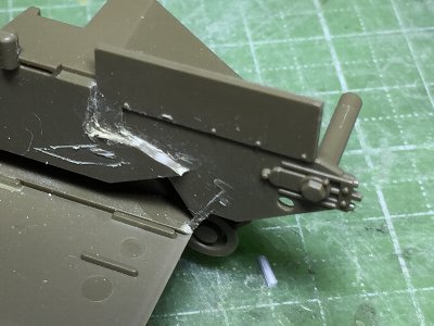
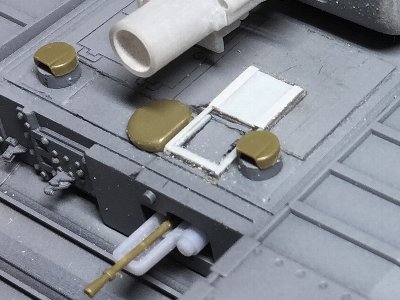 The mortar loading door was made of plastic sheet. The hatch grooves were filled with putty. The ventilator and machine gun were from the kit. |
 The outside phone is in this position. Spare fuel cans, spare tracks, etc. were 3D printed. |
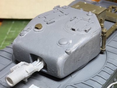 I felt that the front corner of the turret had less roundness. Therefore, the portion was rounded with sandpaper. |
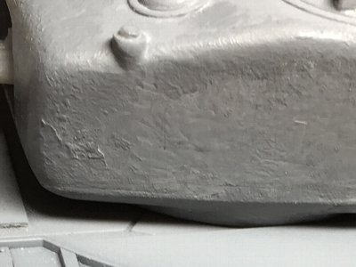 After sanding, cast surface was depicted with melted putty. The cast parting line was depicted by extended sprue and melted putty. |
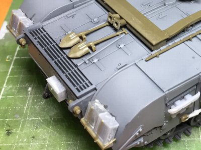
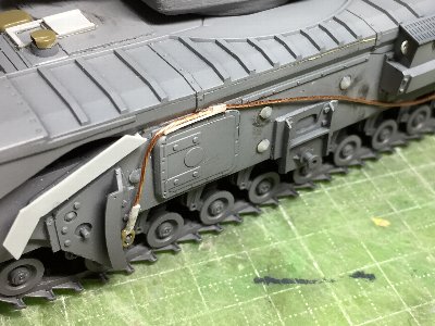 The mud shoot was made with plastic sheet. Wire ropes, conical shape rivets, hanging brackets for the side intakes, etc. were added. |
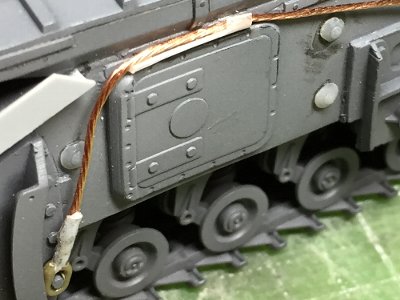 Close-up. The wire rope was twisted copper wire for household electrical cords. |
|
When the periscope visor was glued on the turret, it was too high. So the 3D part were trimmed. The rear rope attachment position of Mk.IV is about 7mm ahead of VII. The upper right image is the position of VII before correction. Probably because the length of the rope is the same, the front mounting position of VII has moved backward. |
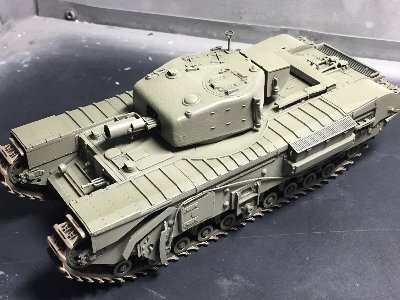
 Detail works was finished. |
|
|
 The base coat is black surfacer + red brown. The silicon barrier was sprayed mainly on the edge where paint was to be removed. |
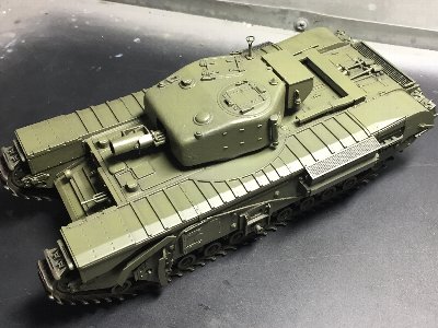 Basic painting is Mr.color C330 Dark Green + 20% white. |
 Tamiya acrylic Buff was diluted with soapy water and airbrushed. After this, Buff was removed by alcohol with tissue paper. |
 Paints on edges were scratched and removed. Excessively removed portions were touched up with a fine brush. Washing was applied with Weathering Master Light Sand or Sand with soapy water. |
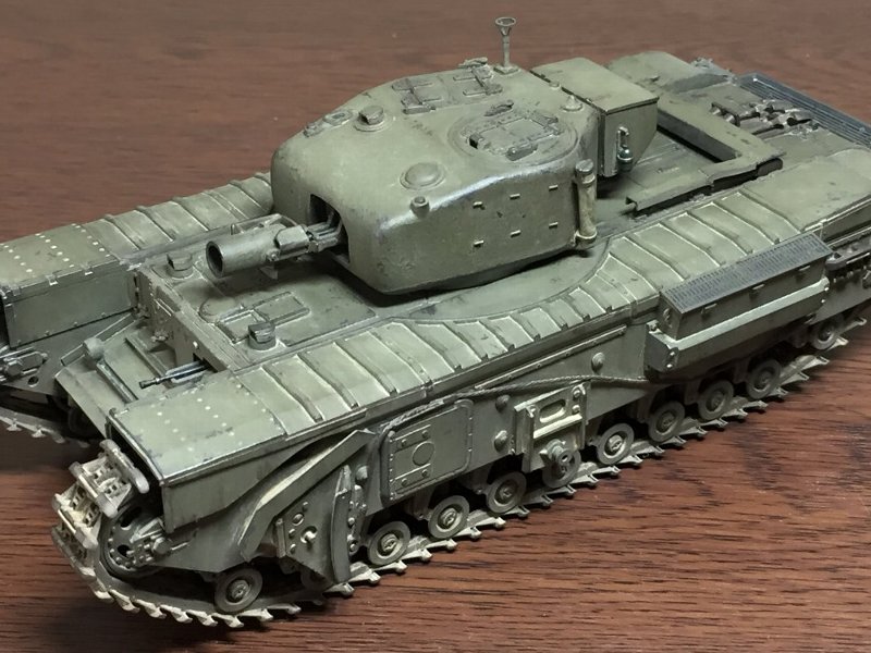 Flat Clear was oversprayed for fixing. Sail Color was airbrushed to the top of the model. Dark gray was airbrushed on edges and corners. Tracks were brush-painted with C22 Dark Earth. Washing was applied with Weathering Master Sand. Rub the edge with pencil powder. Equipment is brush-painted. |
|
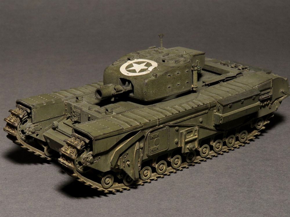
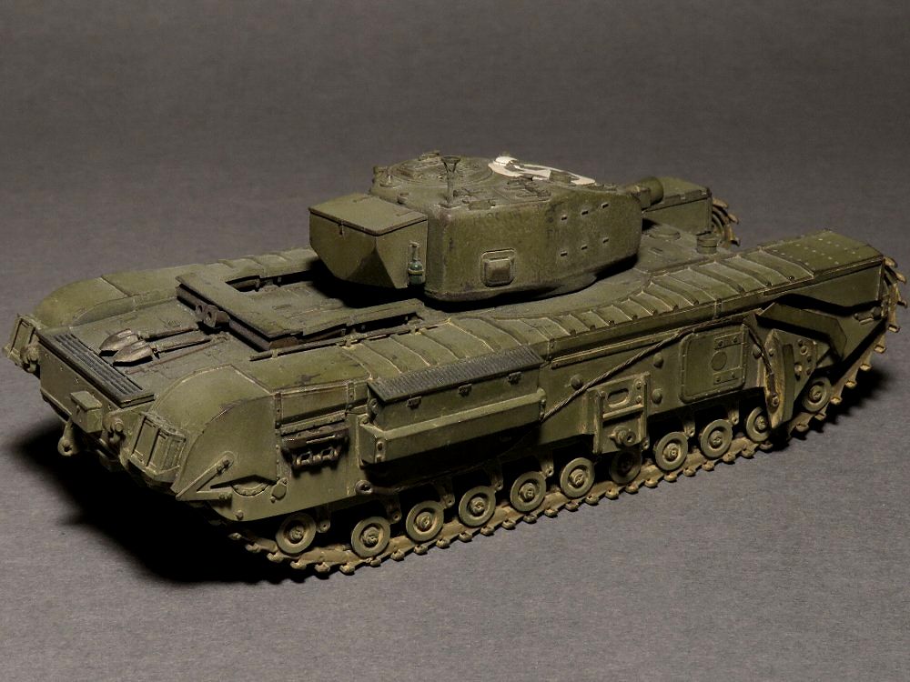
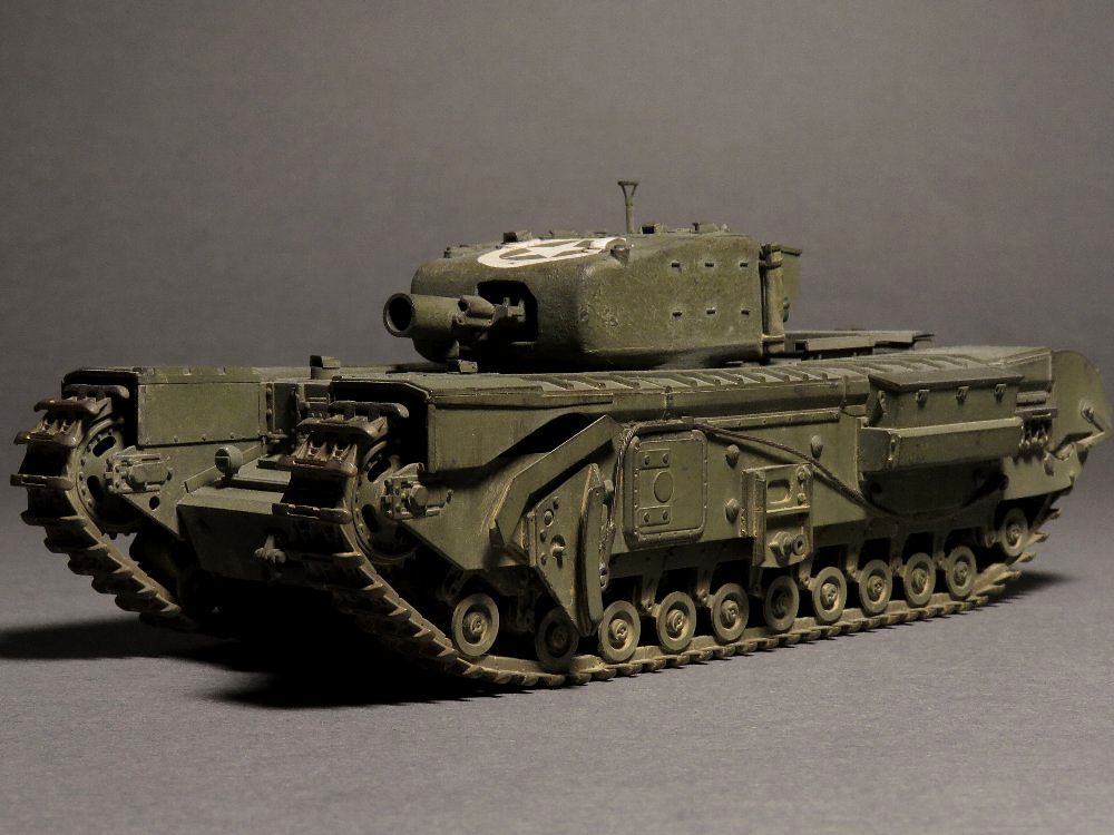
When I look at the completed image again, I think 3D print parts would be a satisfactory level for 1/48. Churchill Mk.III and IV are the mainstreams seen in recorded photos. I am glad if you can use my conversion parts effectively. There are also Mk.III turrets and early crawler tracks. |
|
|
|
 |
|
 |
|
 |
|
 |
 T54E1 with duckbill |
 |
 The back side looks like this. There is also room for rounding corners with Fillet, but I don't do that because the data become too heavy. Still heavy enough. |
 T62 (Download file of T62 has no duckbill) |
 T48 duckbill |
 T51 |
 T54E2 |
 T49 |
 T56 |
 HVSS T80 |
 T84 |
|
 Early M3 type |
 Late type |
 Ring type |
 |
|
|
 Different type duckbill with T54E1 |
 WE210 |
 |
 |
|
|
 |
 |
|
|
 |
 |
|
|
| 1 | Armor At War 7002 D-day tank warfare | Concord |
| 2 | Armor At War 7027 British Tanks of WW2 (1) France & Belgium 1944 | Concord |
| 3 | Armor At War 7028 British Tanks of WW2 (2) Holland & Germany 1944-1945 | Concord |
| 4 | Armor At War 7068 British Armor in Sicily and Italy | Concord |
| 5 | Mr.Churchill's Tanks The British Infantry Tank Mark IV | Schiffer |
| 6 | New Vanguard 4 Churchill Infantry Tank 1941-51 | Osprey |
| 7 | New Vanguard 136 Churchill Crocodile Flamethrower | Osprey |
| 8 | Wydawnictwo Militaria 315 Churchill | Warszawa |