Nakajima Ki43 Army Type 1 Fighter Hayabusa drawings
modeling Ki43-1 modeling Ki43-2
|
|
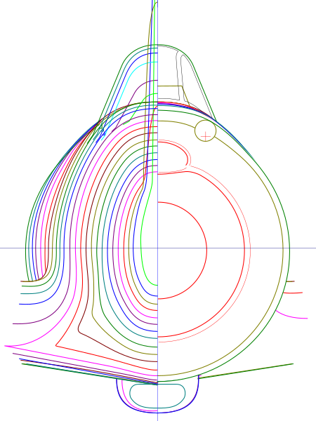
 This is typical mistake of existing drawings. |
|
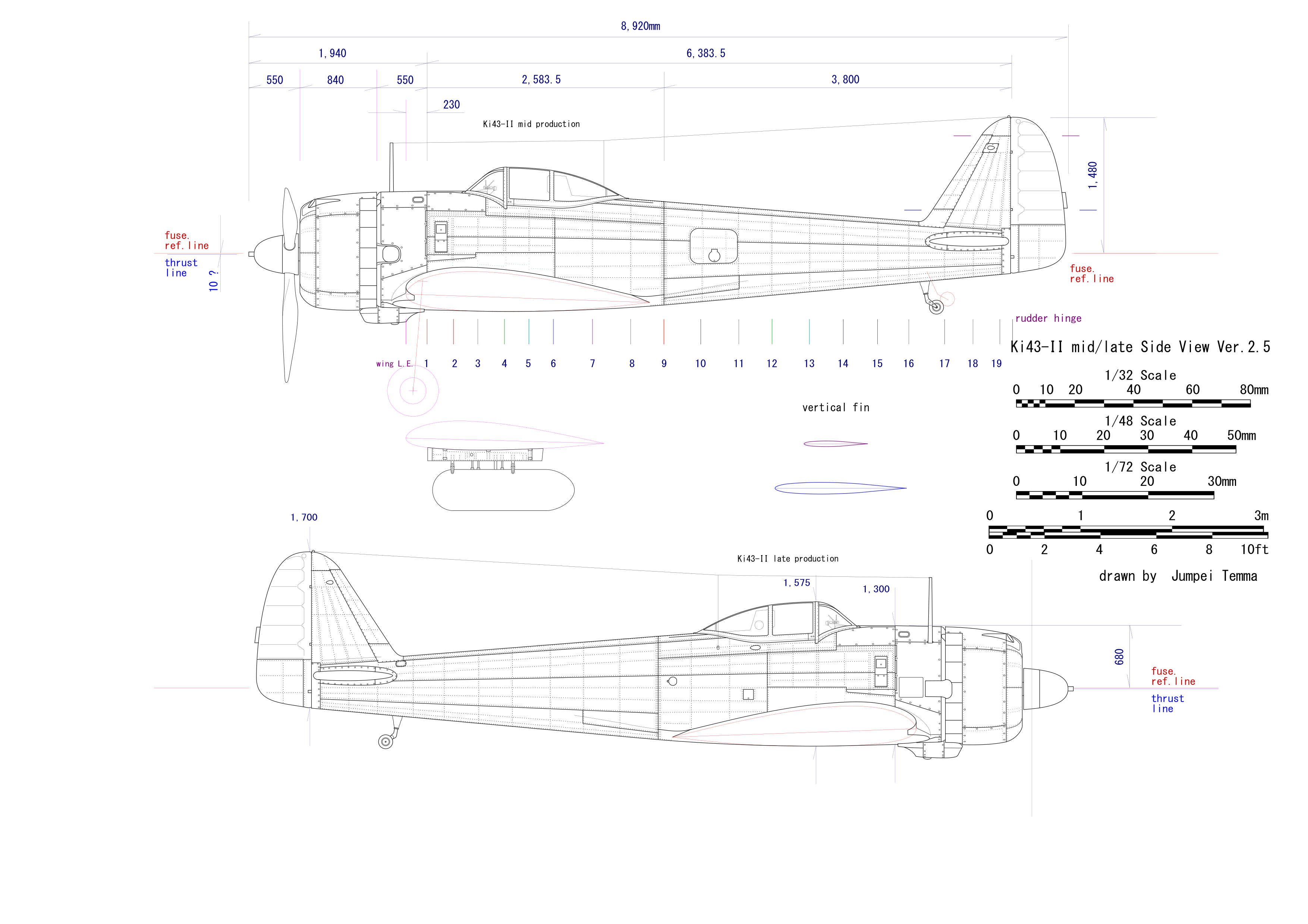
Ki43-2 (Hayabusa II) can be classified in five subtypes by its production period. And there are different naming of five sub-types. One example of naming is ; Kou early, Kou late, Otsu early, Otsu late, Kai (Kai means "mod"). Another naming is ; early-former, late-former, early-latter, late-latter, kai. These naming are not official but expediency for future generations. Official name of these five subtypes is only "Hayabusa II model". So, I'd simply call them ; initial (squarish cowl, ring oil cooler), early (squarish cowl chin oil cooler), mid (roundish cowl), late (concentrate thrust exhaust), very late (separate thrust exhaust). Anyway, this is only expedient naming.
|
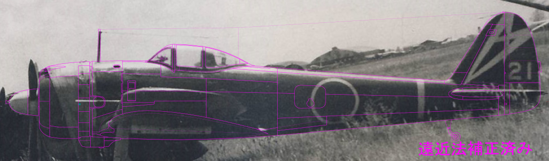
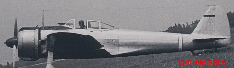 The first photo is from "Koku-fun illustrated no 79". It is mirror-reversed image. Perspective error is corrected by a free image manipulation program software "Gimp-2". As you see the wing tip, the distance is not so far. |
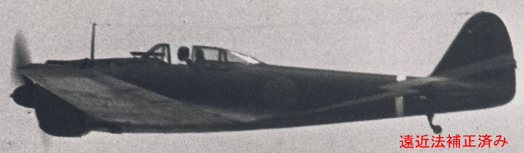 The second photo is Ki43-I of the 50 Sentai. It is far enough but not right beside not so sharp. Perspective error is corrected. |
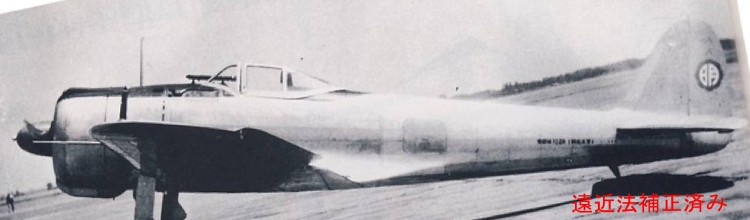 The third is Ki43-I of the Akeno Gakko. This photo is not just fit to the first photo. I think that this original print maybe distorted a little. Moreover, the distance is not far. |
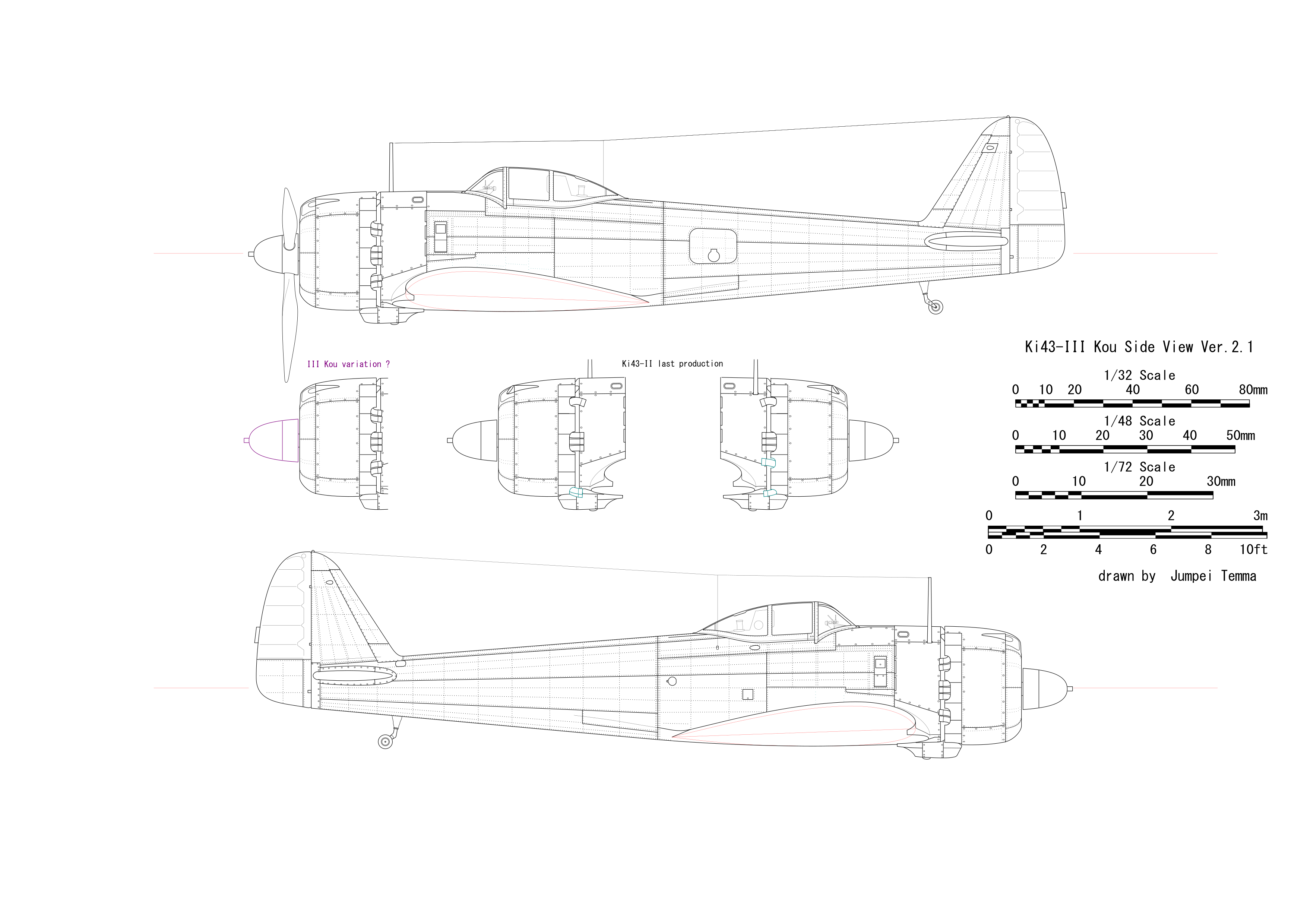
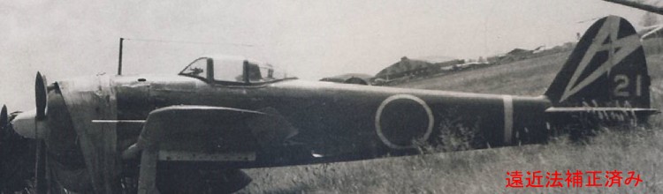 The fourth is Ki43-III Kou of the 48 Sentai. This is the best photo of II and III model for drawings. Sheet on the cowl is obstacle. So the next photo is used complementary. |
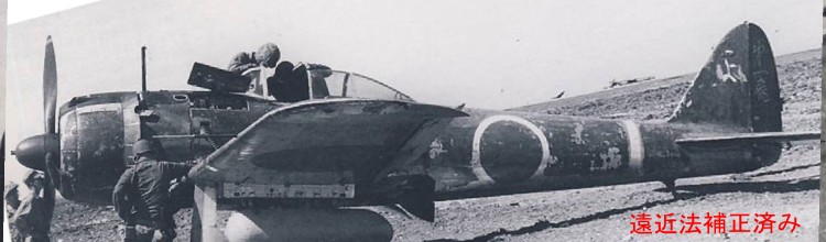 The fifth is Ki43-II very late production. This photo is rather near, but right beside at the cowl and sharp. |
|
How about II/III model? I traced above fourth photo. After some (or vast?) trial and error, I found that II/III is longer by 60mm. The total length of -II was much to above manual data. Mmm... what can I explain...?
|
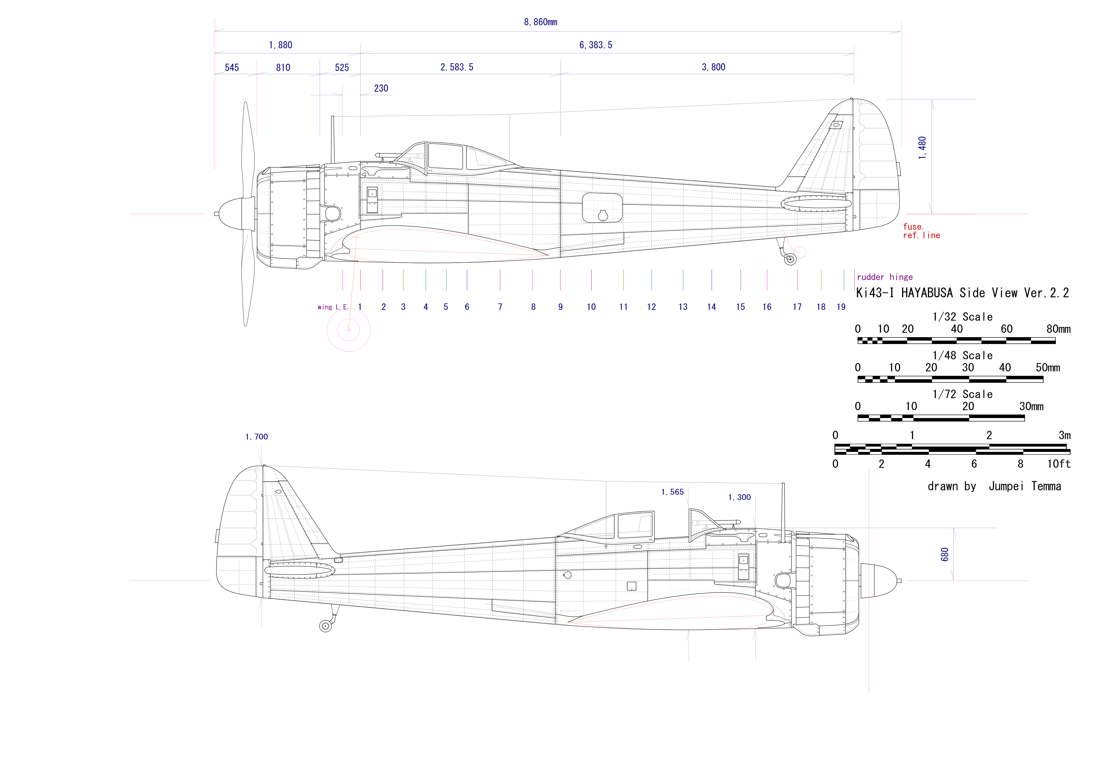
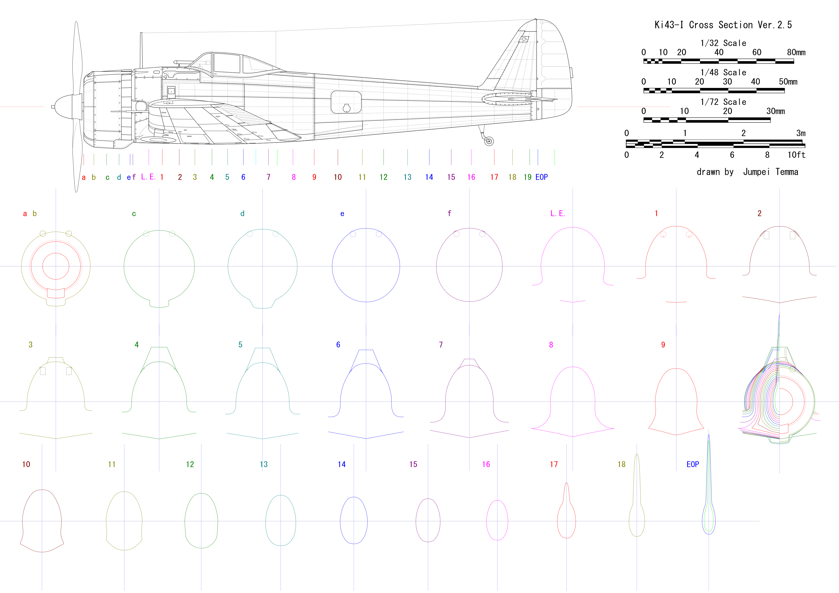
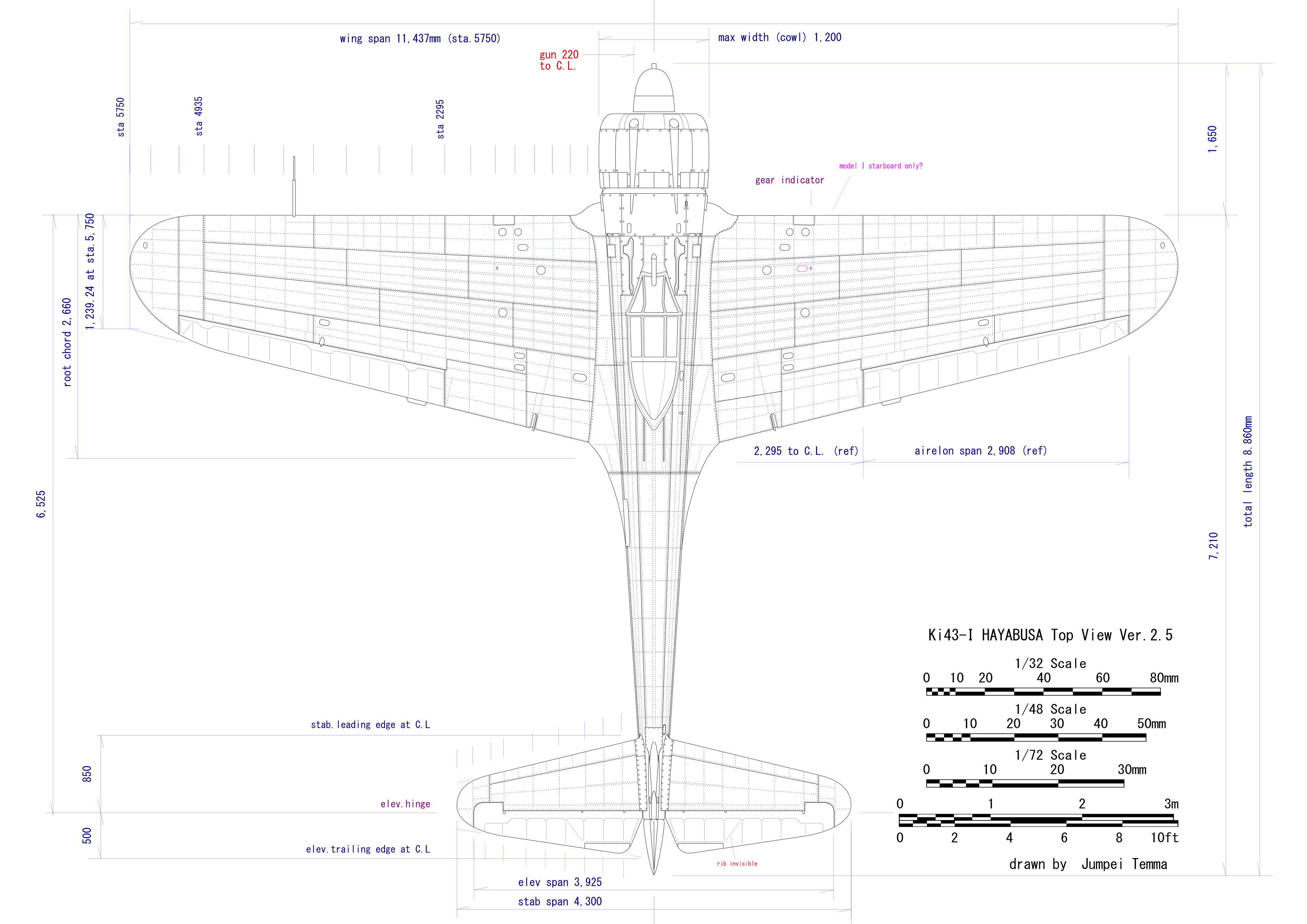
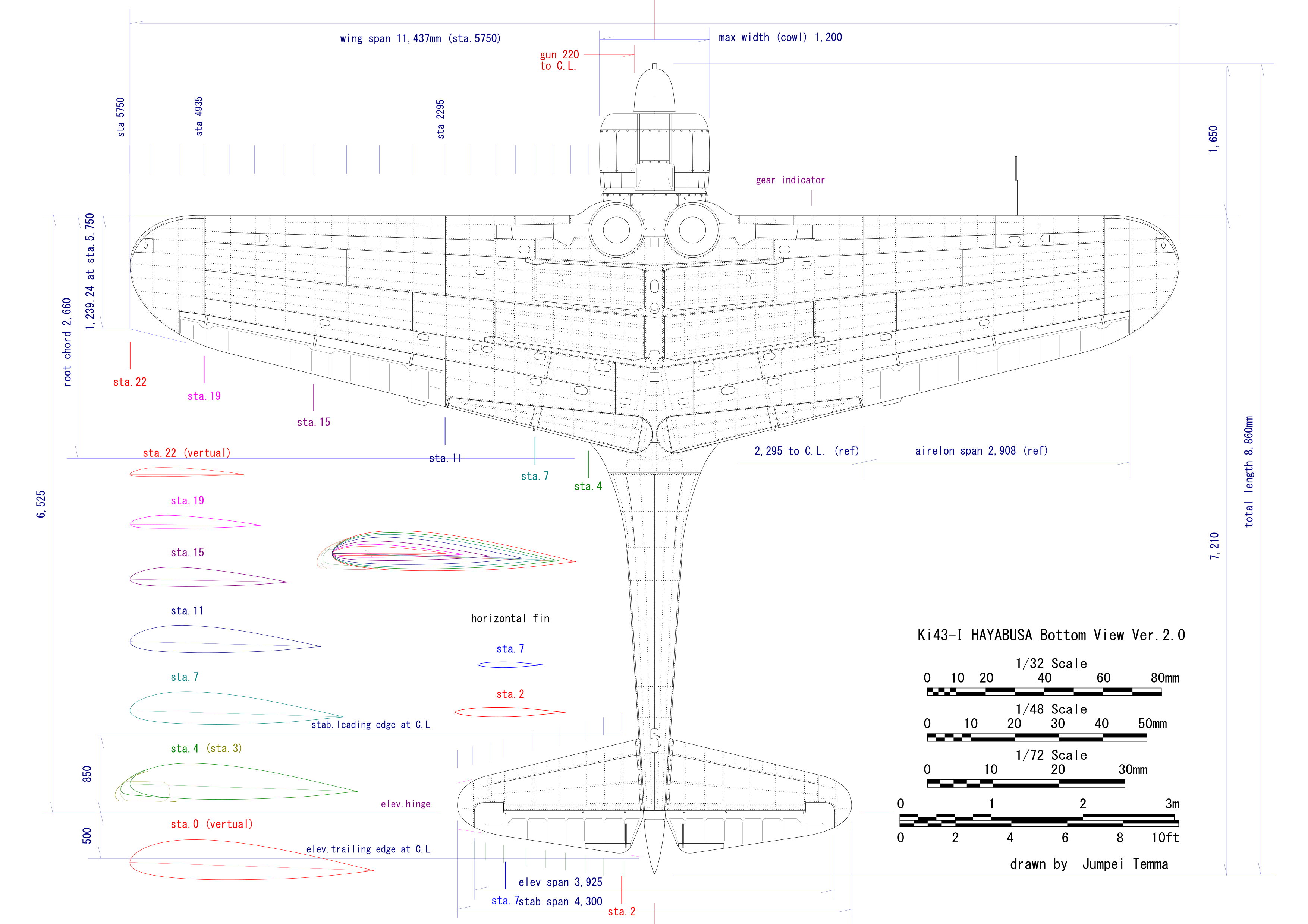
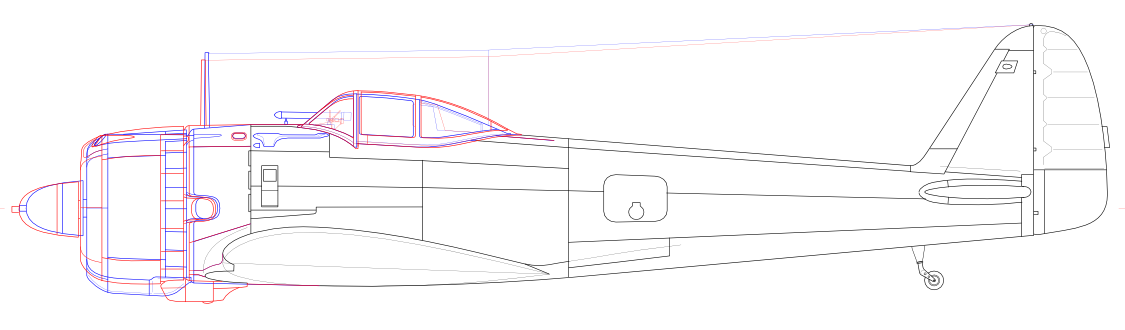
 This is -I model. |
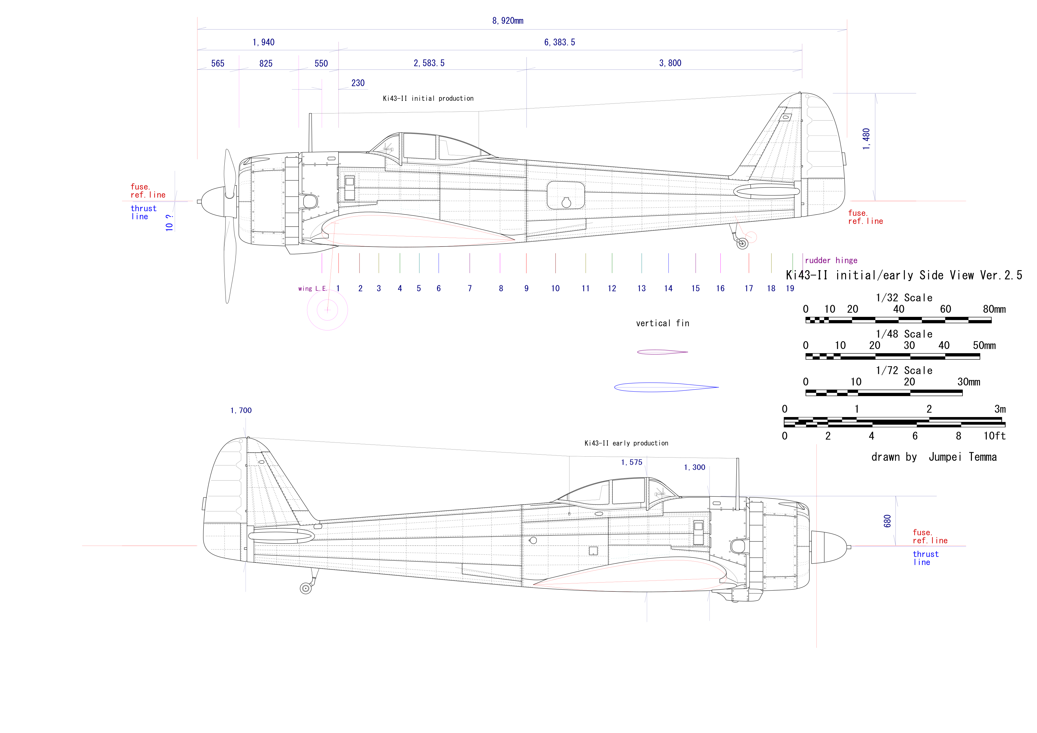
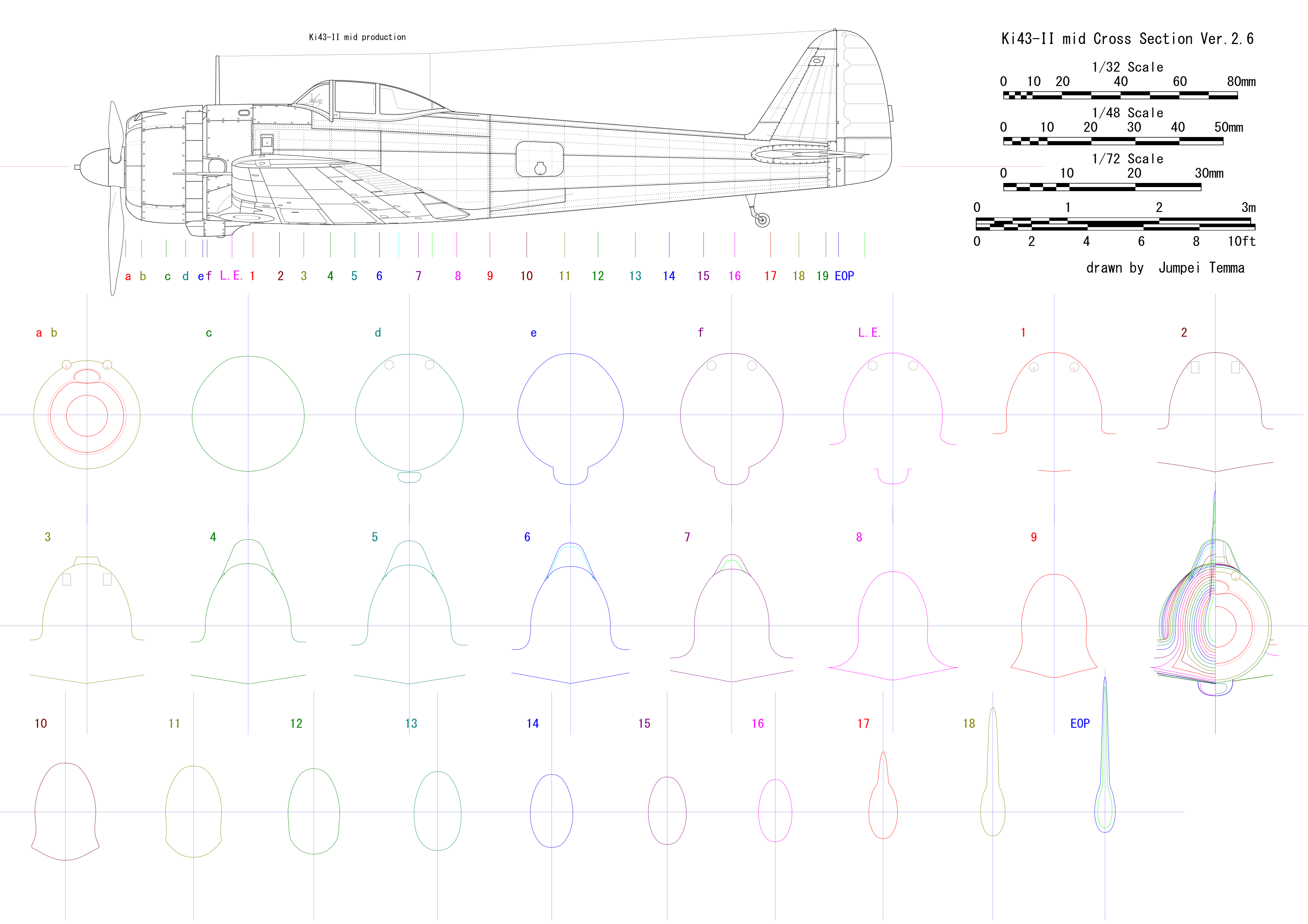
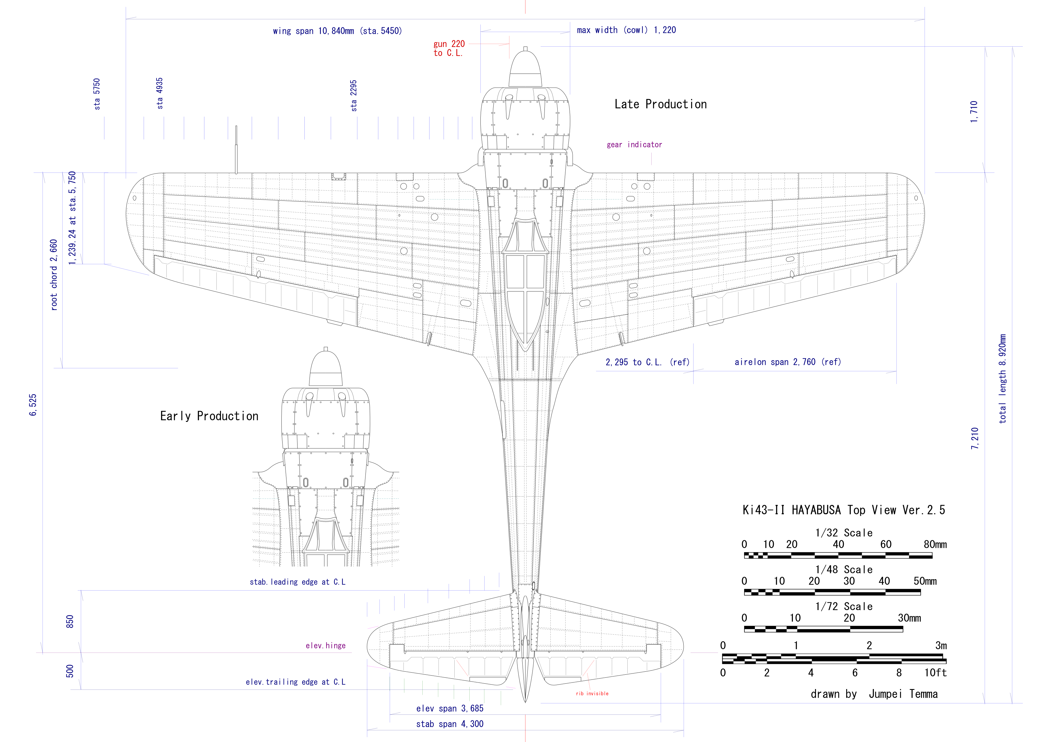
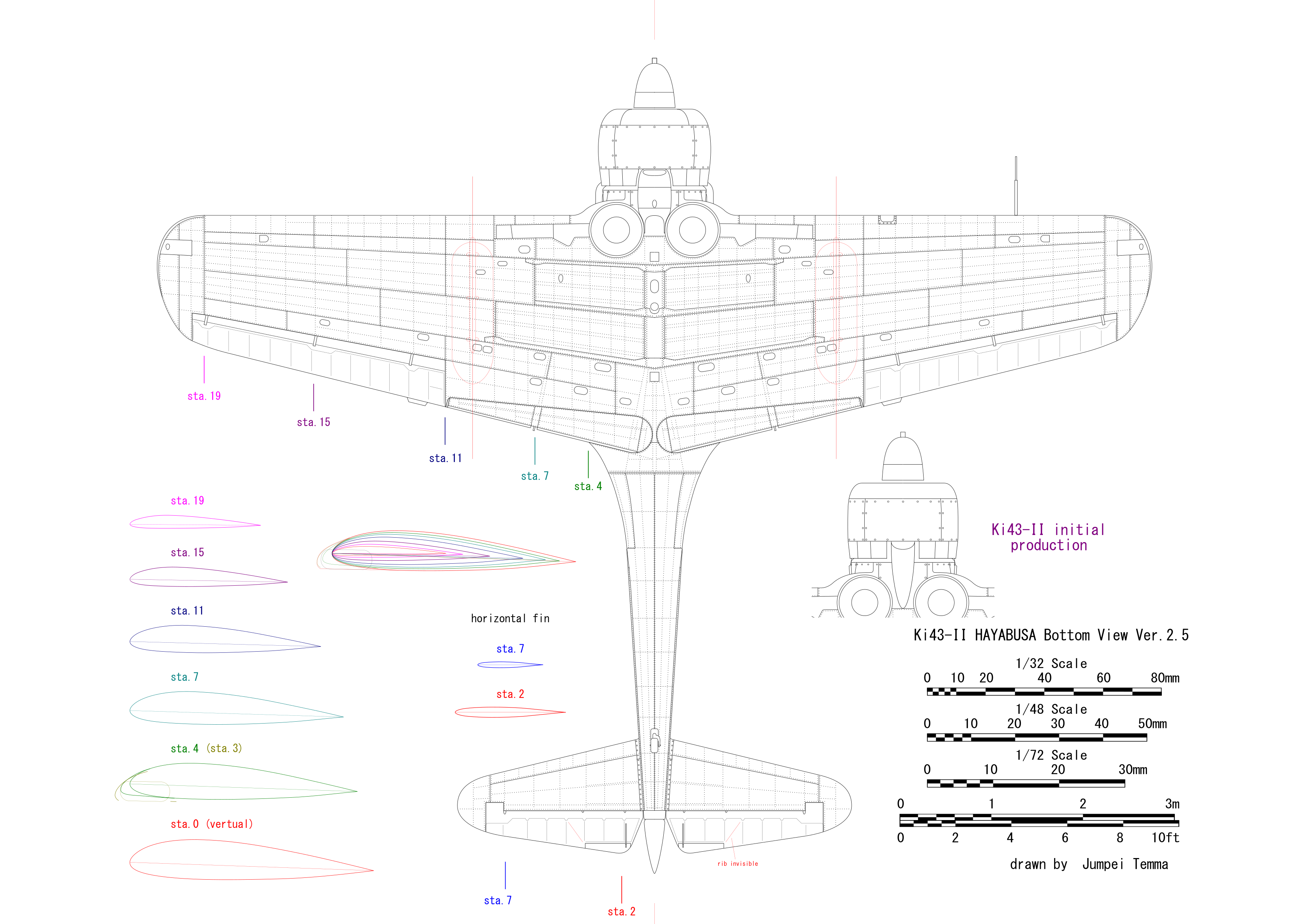
 This is -II model. See the distance form cowl flap to wing bulge. It looks longer than I model. But it doesn't look more than 45mm extended, does it? |
|
|
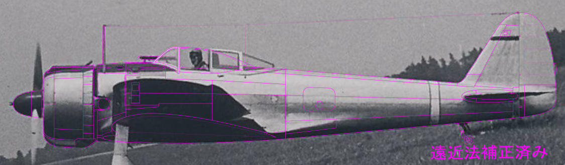 The perspective error is corrected. Upper portion of the fuselage is looked upward. So some lines of drawing are not fit to the photo.
 |
|
|
|
|
|
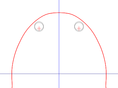
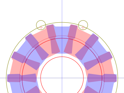 This cross section shows -I model. Red is front row and blue is rear row. + is fire line at engine position with consideration of 1 degree incidence. |
|
The next step is deciding the fuselage cross sectional shape by the gun position. -I model has gun blister avoiding the gun main unit and feed chute. On the other hand, -II doesn't have gun blister. I think the gun access panel of II is not so plump out but the gun position is lowered. If the engine position isn't changed, the fire line incidence is increased. So I think the engine position is lowered as well. In fact, when I compared the photo of actual aircraft, the thrust line looks reduced a little (I assume 10mm in my drawing). |
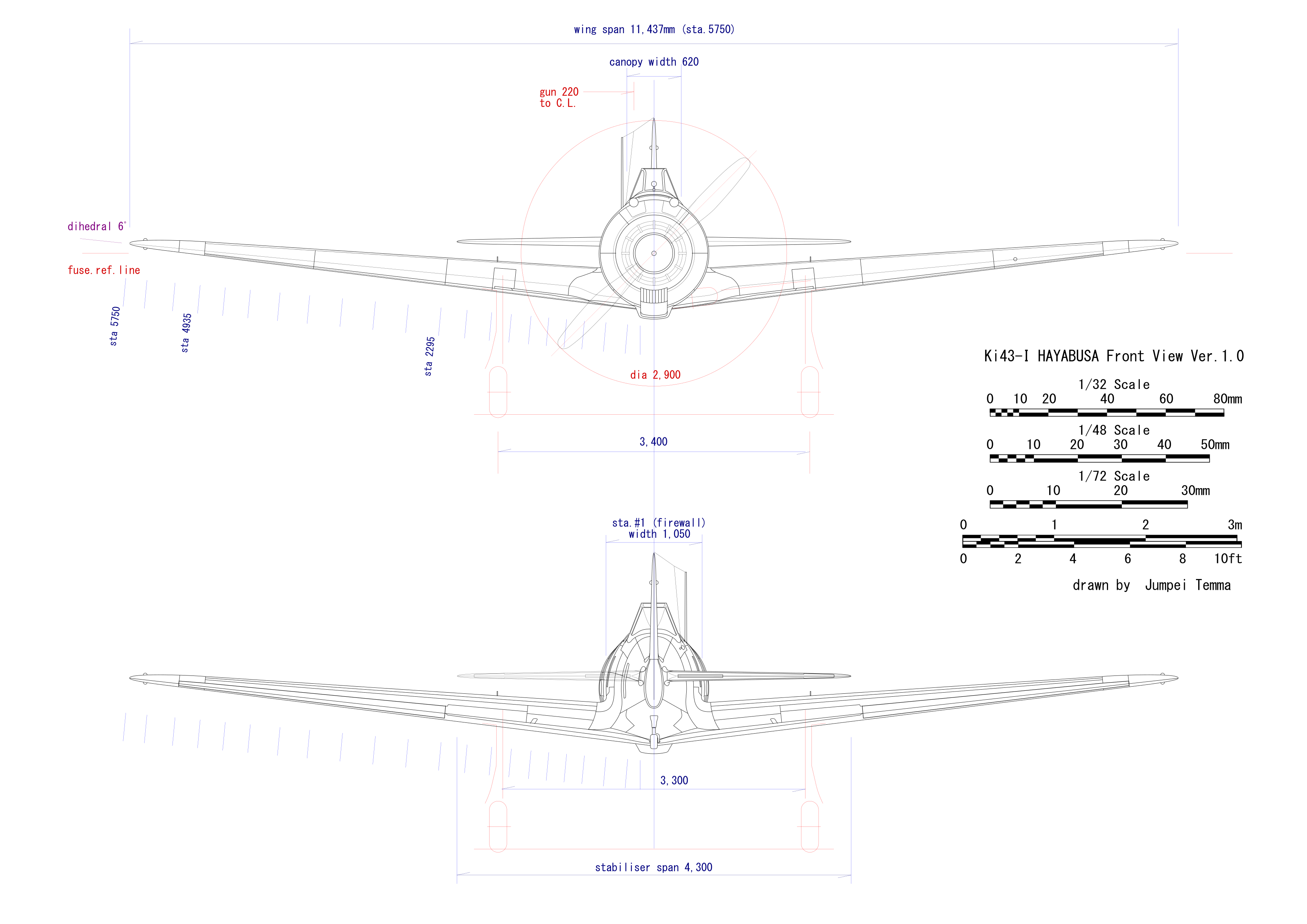
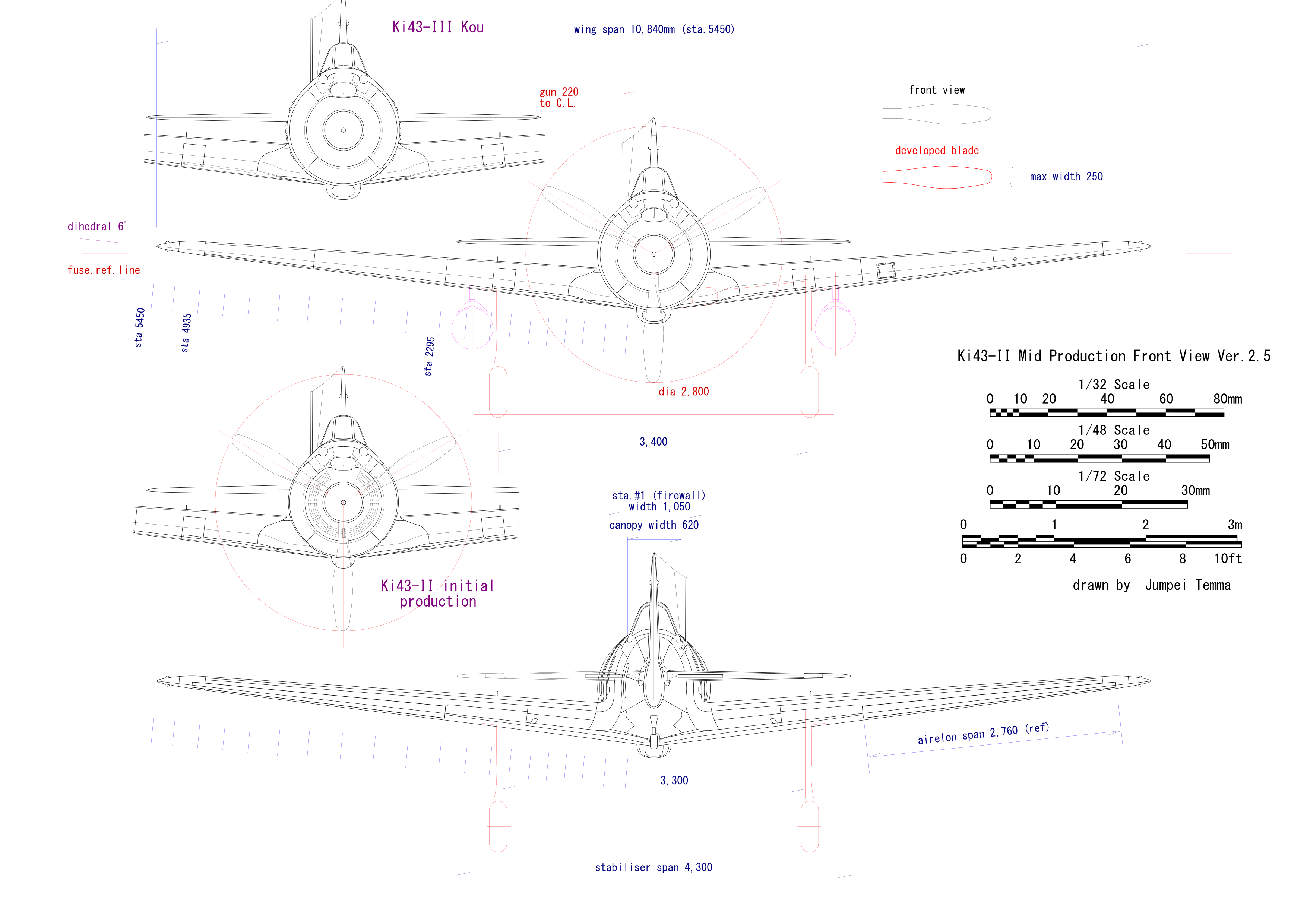
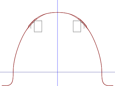
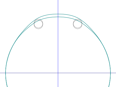 This section is the front edge of cowl flap. Both I and II (mid) are shown in this figure. Two and ten o'clock are not so plumped out because of forward and downward visibility. |
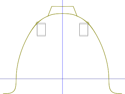
 This is the firewall. I and II are the same shape at this section. The top is flat. The fire line at this section (+) is 507.6mm from ref.line. |
 This is #2 frame. Note the gun main unit and feed chute. I think II is slightly plumped out at this section. |
 #3 frame. the cross section of the wind screen is common in this section. |
|
|
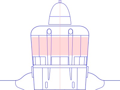
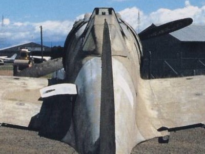 The cross section shape of #9 frame and wind screen can be seen clearly as well. |
|
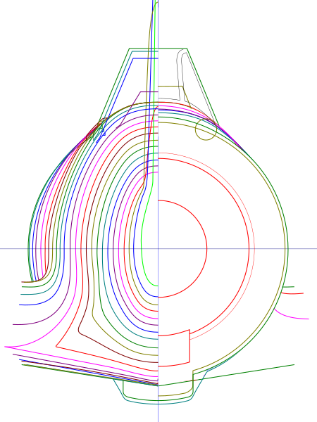
There is a word of caution. This photo is taken from near. So the perspective error should be considered. I corrected this error mathematically and graphically. The result is that the max width of the firewall is assumed 1,050mm and the cowl is 1,200mm (Ha45 is 1,150mm dia.). |
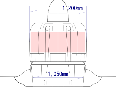 This is the correct shape. |
Typical mistake. |
|
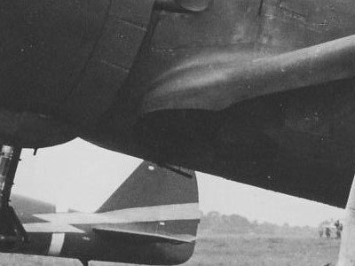
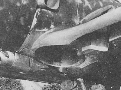
The wing thick ratio is unknown. Different values are described depending on the literature. I assumed it between 16% and 16.5% by analysis of the photo (I used 16.3% in my drawing). The wing position (height) is decided from the side view photo. When the root airfoil is put on the photo, the trailing edge is not match to the lower outline of the side view. Thus, this portion of the lower wing surface should droop down. If you have Tamiya's Zero fighter, see this portion. The cylindrical form of the rear fuselage runs into the wing under surface. But most of Hayabusa kits don't represent this droop, and as the result, the wing position of most of Hayabusa kits are too low. At the same time, the lower surface of the wing front spar at #2 frame droops down slightly. The middle and rear spar are connected to #4 and #6 frame. The lower surface of the middle and rear spar don't droop down.
I assumed the color of the spinner is dark green. Because, the spinner of early production -I is unpainted at the factory finish. This is judged from photos of the early -I of Akeno Gakkou. The late production -I and II/III are painted in red brown in the factory. The back face of the blade is red brown. Many modeler (even misunderstand it as black. Small quadrilaterals on the tail are unpainted areas where the serial number is painted. Unfortunately, the number is unknown. |
|
|
|
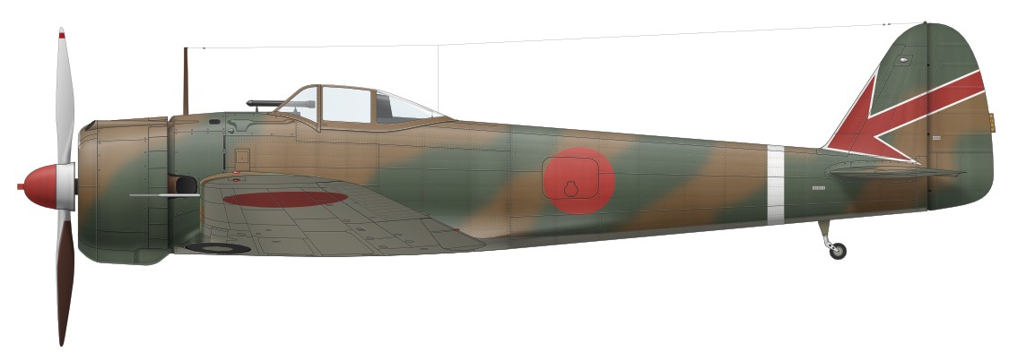
The next two tone camouflage is Hayabusa I Hei of the 2nd Chutai 64th Sentai, Malay Peninsula, March 1942. The photo was taken from the starboard side and the camouflage pattern is a supposition. Some existing color profiles are illustrated without fuselage insignia. I assume Red and Green are invisible in a monochrome photo. I assume the color of the latter half of spinner is white. But it cannot be decided which white or silver. |
 |
|
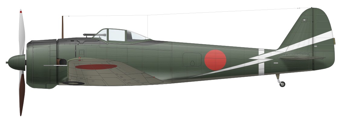
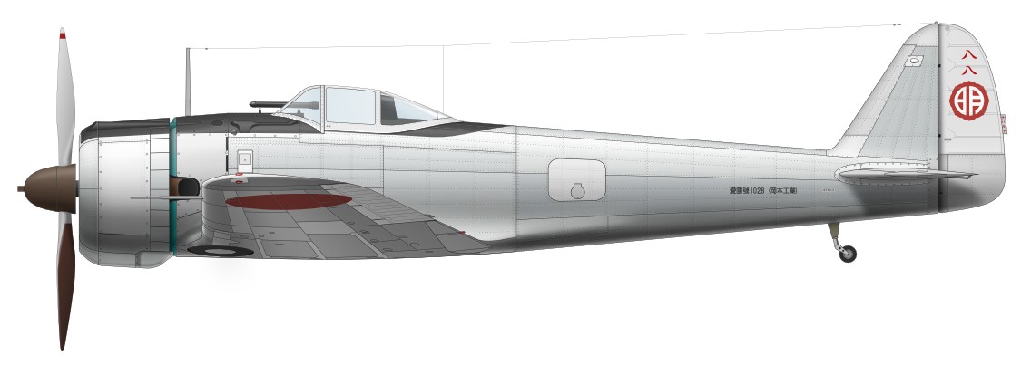
This natural metal finished one is Hayabusa I Hei of the IJA Akeno Hiko-Gakko (Akeno Flying School), serial 388, Aikoku-Go (patriotism dedication aircraft) no 1028, in spring 1942. I don't have a confirmation of the color of the spinner. The last two digit of serial (88) is painted on the rudder. It has a possibility of black. The front of the fuselage rearward cowl is painted Aotake (clear greenish blue). |
 |
|
The next is Hayabusa II early production flown by Captain Nakakazu Ozaki CO of the 2nd Chutai (squadron) 25th Sentai, Nanjing China, in summer 1943. The upper surface is painted over dark green monotone. So it has a possibility that the under surface is painted in light green gray. |
 |
|
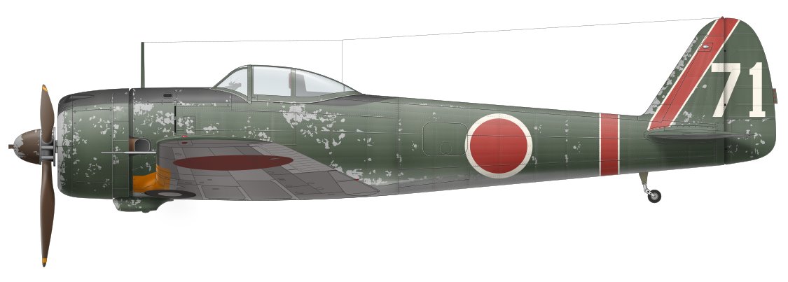
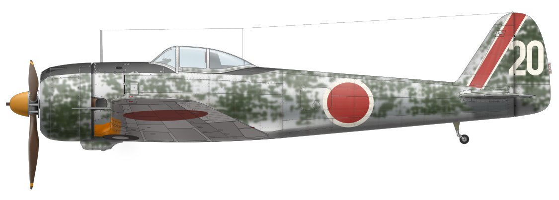
The next one is Hayabusa II mid production of the 25th Sentai, Nanjing China, 1943. Many of the 25th Sentai's aircraft don't have latter half spinner panel. The landing light on the port wing leading edge was introduced sometime around -II late production. So this aircraft don't have the landing light. Note the difference of outline image of the cowl between -II early and -II mid. Also, note the clearance between spinner and cowl. |
 |
|
Fujimi 1/72 -I Fujimi 1/72 is a good kit which well represent rugged outline shape of actual -I model. When its fuselage part is joined together with Hasegawa 1/72, the outline is not much each other. They have good and bad points and the correct outline is different from each one. The cross section shape of firewall is not a trapezoid but an ellipse. The height of the canopy is low, and as the result, the fuselage is high at this rate. The cowl side is roundish as like as -II's cowl.Hasegawa 1/72 -II Hasegawa 1/72 is a good kit as well. The outline shape of its roundish cowl is well represented. The total length of the fuselage is a little long. The cross section shape of the firewall is the same as Fujimi. The canopy and propeller are poor as like as Hasegawa Ki84 Hayate. The vertical position of the wing is a little low.Hasegawa 1/48 -I The outline shape of the cowl, fuselage and canopy are good. Hasegawa is the best of all 1/48 kits as for these points. Regrettably, the vertical position of the wing is rather low. So the lower wing droops down in the side view profile like a pregnant woman. The trapezoid shape of the firewall is not represented.Hasegawa 1/48 -II/III I don't have this kit. But I heard that the rear fuselage is inexplicably deeper than Hasegawa -I.Finemolds 1/48 -II/III The outline shape of the cowl and fuselage are not so good. The cowl side is not roundish but like a cylinder. The trapezoid shape of the firewall is not reprexented. The firewall is too wide and roundish.Nichimo 1/48 -I Some old modelers highly recommend this kit. But I don't think so. The outline shape is not good. The value of this kit is a nostalgia.Hasegawa 1/32 -II The outline shape of the cowl and fuselage is not good. The expressive transformation of the cross section shape of actual fuselage is not represented. The kit' fuselage is like a baseball bat. I want a new tool 1/32 kit!LS (Arii) 1/75 -II This kit is a nostalgia as like as Nichimo. The fuselage is 1/75 scale, but the wing is 1/72.Sweet 1/144 -I Sweet is developing a new tool 1/144 kit. I gave all-out cooperation for them. So, I am very much looking forward to it. I highly recommend it.
|
| 1 | The World Famous Airplane of the World No.65 Army Type I fighter Hayabusa (New Eddition) | 4-893-19062-8 | Bunrindo |
| 2 | The World Famous Airplane of the World No.13 Army Type I fighter Hayabusa (New Eddition) | - | Bunrindo |
| 3 | The World Famous Airplane of the World vol.1 Army Type I fighter Hayabusa (Old Eddition) July 1972 | - | Bunrindo |
| 4 | Koku-fun Illustrated No.79 A Record of The Army Airfoece vol.1 | - | Bunrindo |
| 5 | Koku-fun Illustrated No.80 A Record of The Army Airfoece vol.2 | - | Bunrindo |
| 6 | History of Pacific Warfare Series 52 Army Type I fighter Hayabusa | 4-05-604181-4 | Gakken |
| 7 | Aero Detail No.29 Nakajima Army Type I fighter Hayabusa | 4-499-22735-6 | Dainippon-Kaiga |
| 8 | Military Aircraft Mechanical Series No.12 Hayabusa / Shoki / Kyunana-Sen | 4-7698-0921-2 | Kojinsha |
| 9 | Airworld Special Number J&P No.1 - 3 | - | Airworld |