North American P-51A Mustang
Accurate Miniatures 1/48 part-1
|
|
|
|
 |
 |
|
|
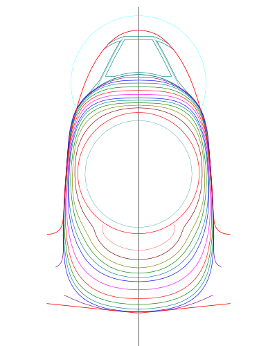
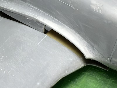
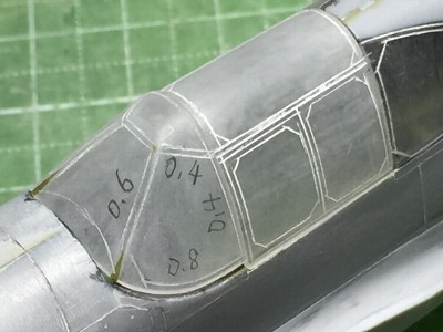
 The kit cross section shape is roundish. The upper air intake was cut off. |
 The bulkhead was cut out from 0.5mm (.02") plastic sheet. |
 The kit nose cowl was cut at panel lines. Each piece was bent to correct shape and glued on the bulkhead. |
 The bent portion changed whitish. Bulkheads have a role of reinforcement. They keep the shape rigidly. |
 The outer surface was sanded to the correct shape. The air intake was rejoined. |
 Plastic sheet was glued on the inside for reinforcement. Mortise joints were installed. They kept left and right fuselage position at the time of sanding. |
|
|
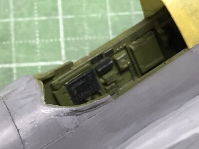
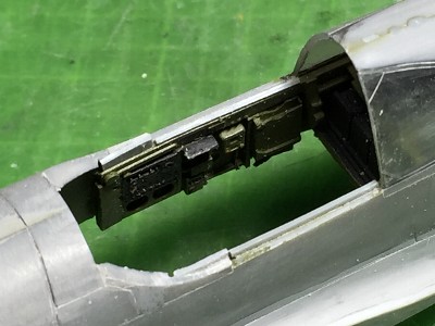
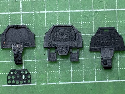
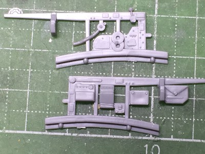 Kit cockpit parts. |
 Aires resin parts. |
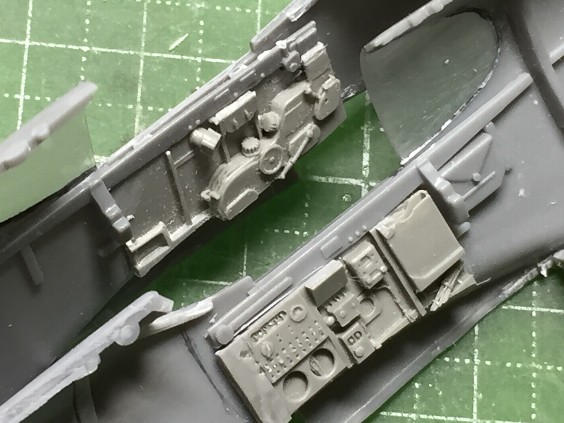 They were glued on the fuselage inside. |
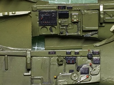 The cockpit was painted and weathered. |
 The seat and bullet proof plate were from Aires. The floor (to be exact, the upper wing surface) was from the kit. |
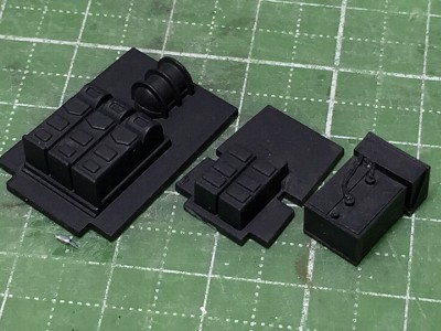 The left two parts are kit parts. The right is Aires. |
|
|
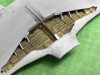
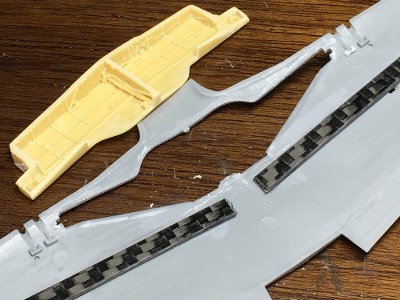 The front side wall and ribs were deleted in order to fit the kit wing. |
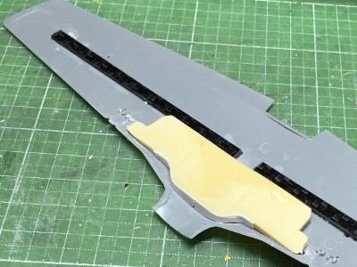 The carbon fiber rods were glued for reinforcement. |
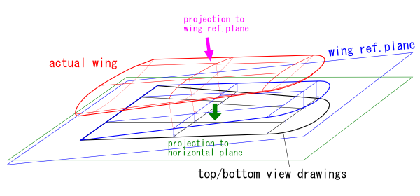
 The upper parts were glued with care for wing specs. The dihedral is 5��(wing ref.line) or 6.2��(lower surface). The incidence is 1.05�� (root) and -0.85��(tip). |
 The leading edge of the wing bulge is droop down. So, the bulge looks small in the front lower view. |
|
The leading edge line is bent at the bulge in front view. The kit wing is insufficient regarding this bent.
|
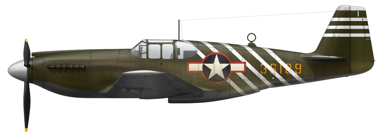
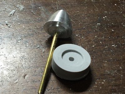
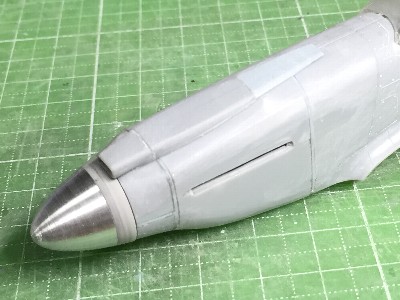
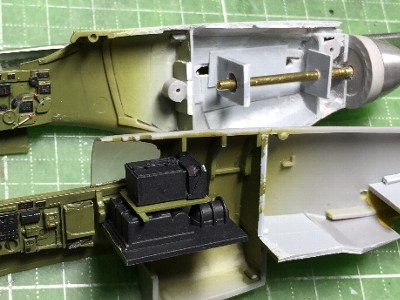 The propeller axis was held with two pieces of plastic sheet. These were glued slowly with liquid cement. This method enables exact positioning of the axis. |
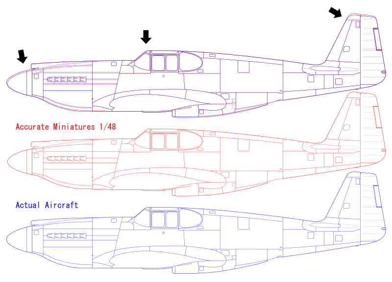
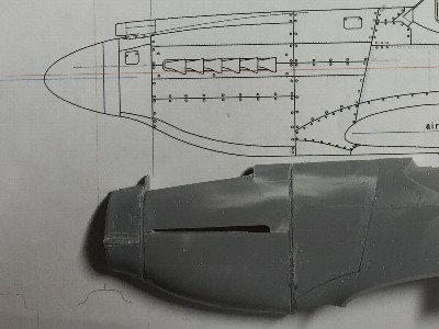
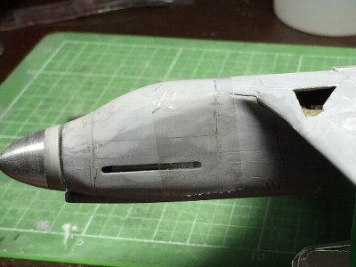
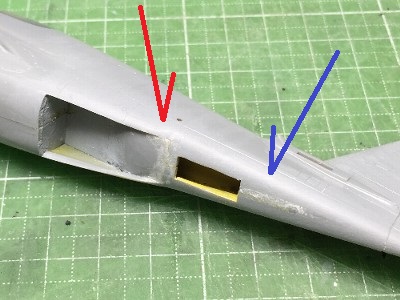 The corner of the lower fuselage was too squarish (blue arrow). So the edge was sanded to be roundish. The shape of radiator outlet side end was corrected (red arrow). |
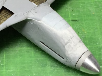 The nose correction works had been insufficient. Plastic sheet (gray portion) and CA glue with plastic powder (white portion) were put on. |
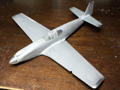
 The side view was checked. See the straight line of the lower side. |
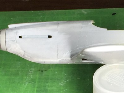
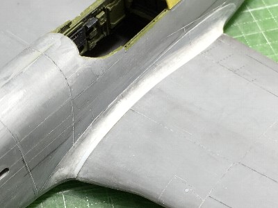
 The fitting of the wing and filet was adjusted with CA glue and plastic powder. |
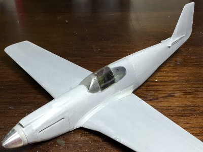 The overall shape appeared. The fin tip was cut by 2mm (.08"). |
|
|
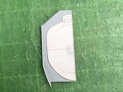
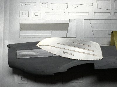 Cutting sheet was used as template. |
 |
|
|
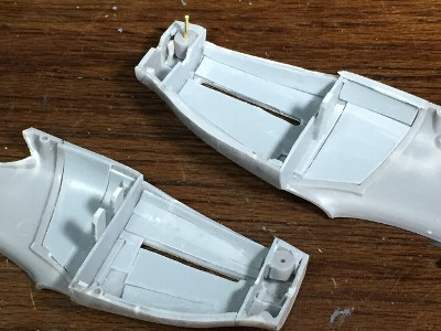
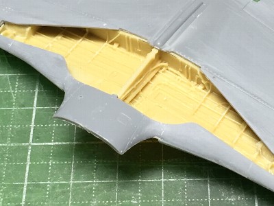
 Ribs of the gear bay were made of plastic sheet. |
 The wheel door was glued. |
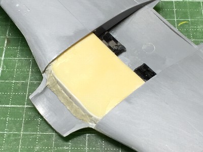
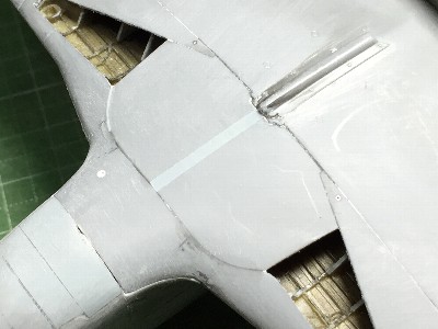
 I couldn't satisfy the position of the wing. I found that the kit wing position was a little low. |
 Then the wing position was raised by 0.5mm (.02"). The gap between the filet and wing was filled with CA glue and plastic powder. |
|
|
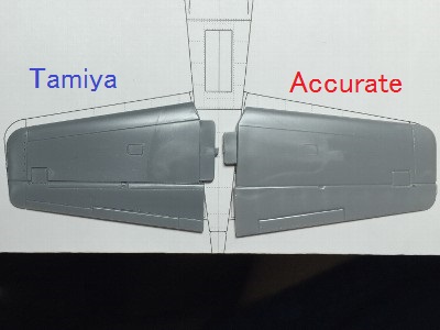 The left is Tamiya, the right is Accurate Miniature. |
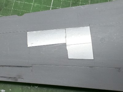
 The joint line was adjusted with plastic sheet (gray). |
|
|
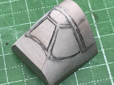 Then I made wooden mold of chemical wood. |
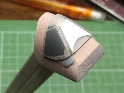
 This is the kit wind screen. The silver sheet is correct shape of the window. See the kit window side frame located outward. |
|
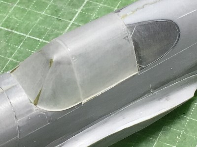
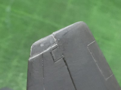
The demarcation line of the kit wind screen and fuselage is just the edge of window glass. So the glue line might be seen through the clear window. In order to prevent from such situation, the glue line of the fuselage was cut by 1mm (.04"). |
 This is the kit fuselage glue line. The pencil marked portion is to be cut. |
 The glue portion was cut. |
|
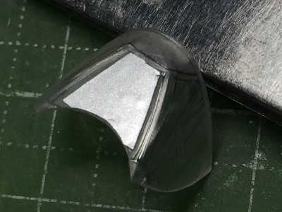
Tamiya 0.4mm (.02") Plaban (clear plastic sheet) was cut as 20 x 20cm (8 x 8"). Sheet was held by hands with thick heatproof gloves and was heated over a small flame of the kitchen stove. Melted clear plastic shrinks and thickens. Then press it on the wooden mold. Cut out and sand the inside and outside surfaces. |
 The wood mold is fixed on a wood rod. |
 The heat formed wind screen was sanded together with kit center canopy portion. |
 Template for the wind screen was cut by cutting machine. |
 Window frames were engraved with a custom made double needle. |
|
|
 The left is Aires, the center is Accurate, the right is Tamiya. |
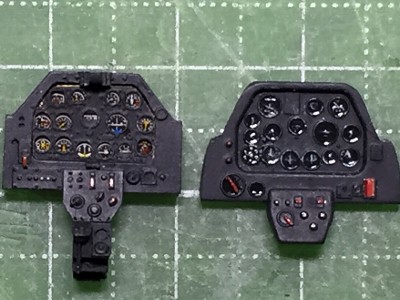 The left is Aires, the right is Accurate. Aires's resin portion had shrunk so I had to trim the photo etch panel. |
|
|
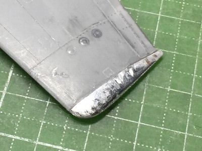
 The plastic surface of the fin tip was peeled off by 0.3mm (.01"). |
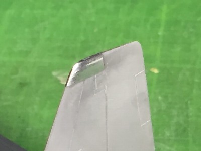 0.2mm (.008") thick aluminum sheet was anealed, formed, trimmed and glued with epoxy glue. |
|
The top view shape of the kit wing tip was corrected before aluminum works. The front curve was to be roundish. Then 0.3mm (.01") aluminum sheet was applied. |
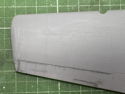 This is the original kit wing before correction. |
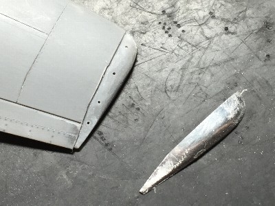 Here is the starboard upper wing. The aluminum portion was cut down. Aluminum sheet was formed. Small holes were for eduction of excess glue. |
 Here is the port lower wing. The edge of upper side aluminum sheet can be seen. |
 Lower aluminum sheet was glued. |
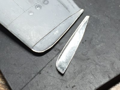
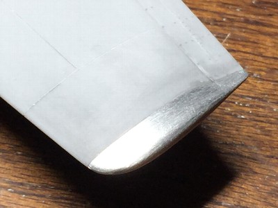 The surface was sanded with #600 to #1000 grit sand paper. |
 Aluminum works were finished. |
|
|