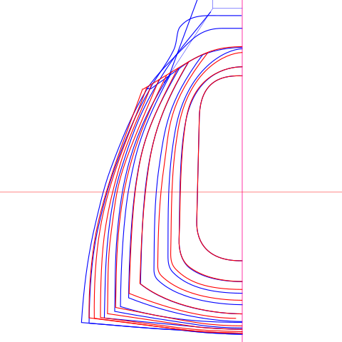
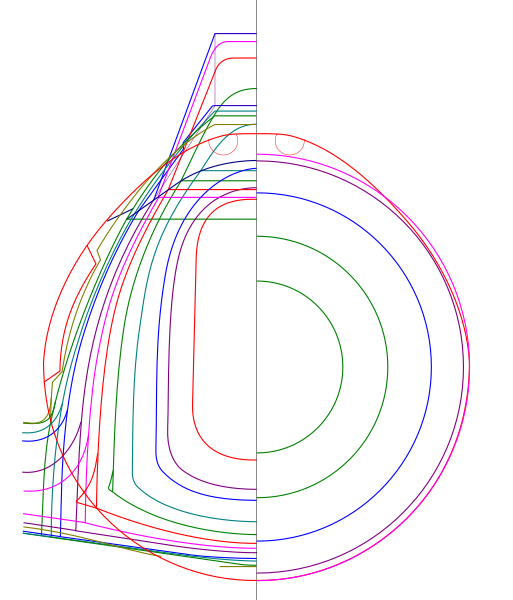
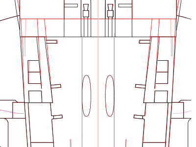
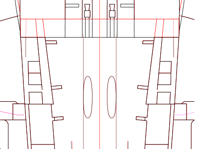
This is the trace of the contour diagram. Red lines are Fw190. Blue ones are Ta152. Note that the cross-sectional positions of the two do not always match in the above image. Why do not they match?
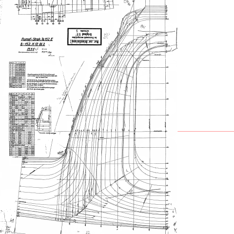
This is the Ta152 contour diagram.
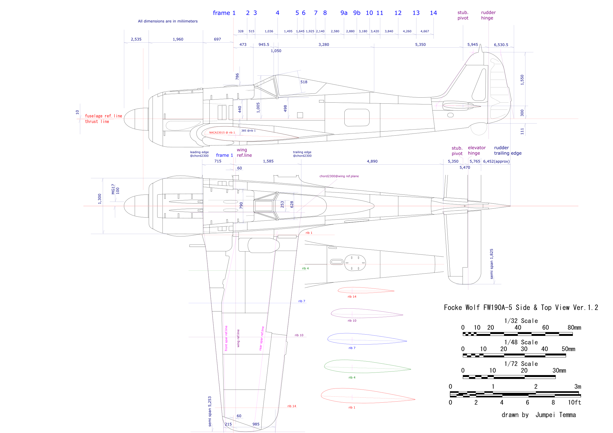
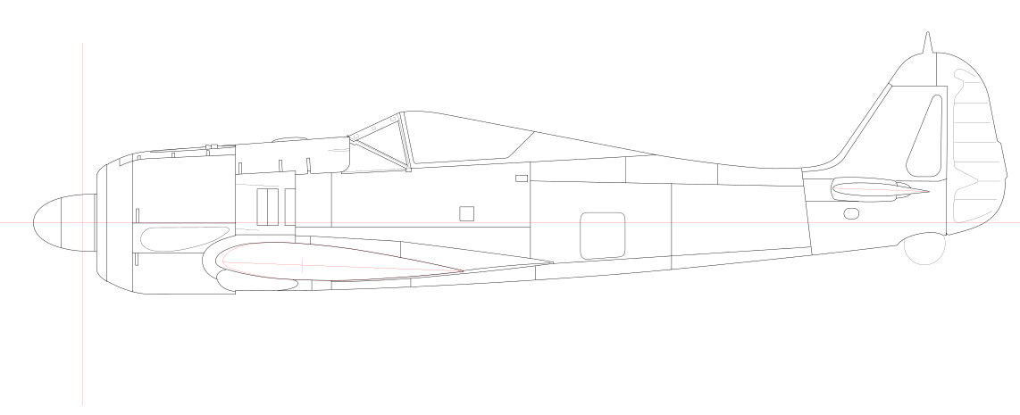
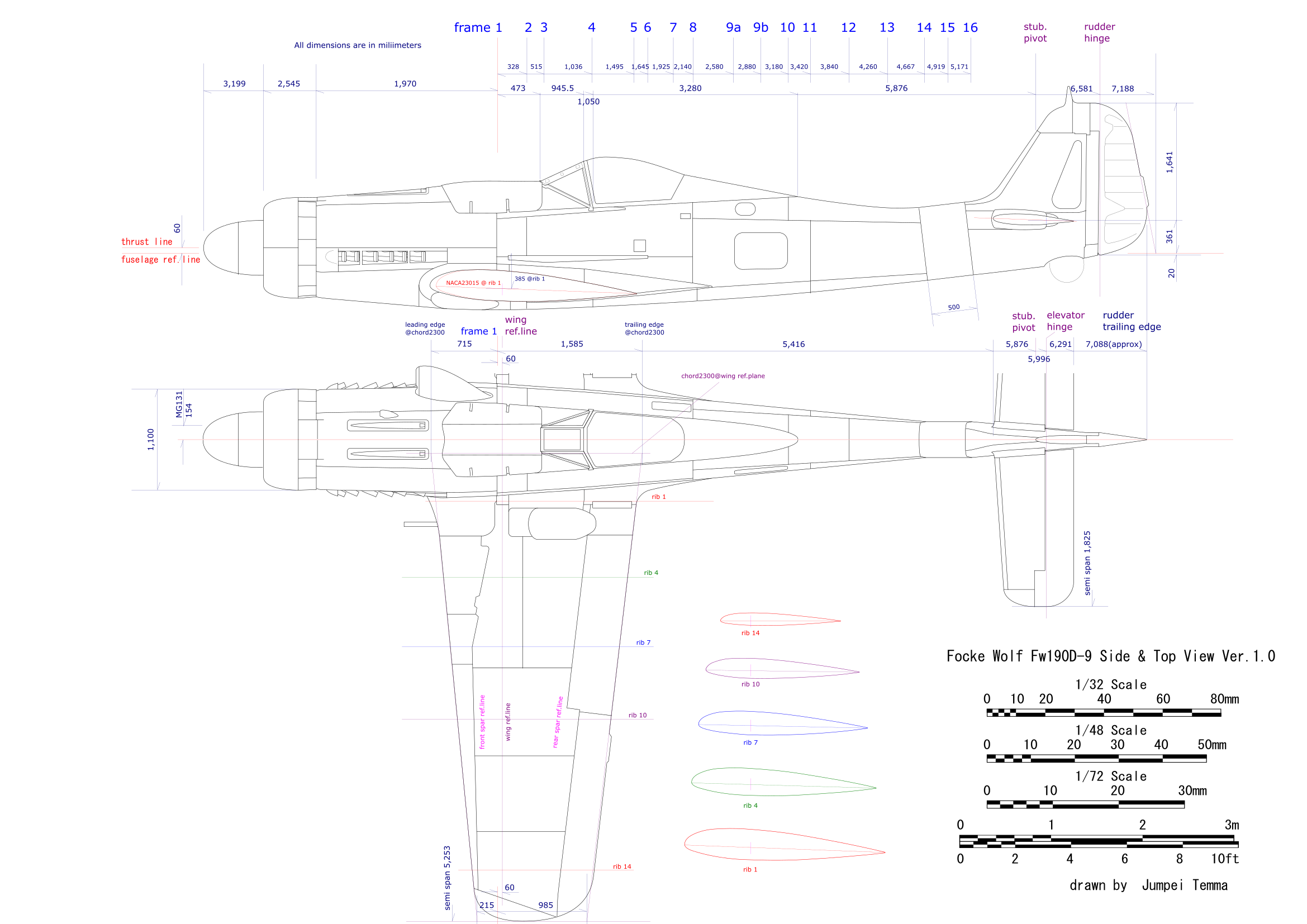
Focke Wolf Fw 190 Drawings
2019.8.14初出
|
|
|
This is the trace of the contour diagram. Red lines are Fw190. Blue ones are Ta152. Note that the cross-sectional positions of the two do not always match in the above image. Why do not they match? |
This is the Ta152 contour diagram. |
|
From the development process of Ta152, the basic fuselage shape of Ta152 and Fw190 should be the same. If so, only one is correct. Here, paying attention to the line at the top of the fire wall, the drawing written as Fw190 does not lead to the cross-sectional shape of the gun cover (← you can see it immediately by actually drawing it). Furthermore, as I could know the dimensions of the windscreen rear end frame from another factory drawing, the fuselage width of Fw190 was wider than the windscreeb frame. Therefore, I judged the contour diagram of Ta152 was correct. It is unknown why the drawing called Fw190 is different. Is it a prototype?? The height of the lower surface of the fuselage between Ta152 and Fw190 is different, because the wing mounting position is different. Although it was suspicious, I adopted the Fw190 drawing as for the height of that. The next question was where each line in the contour drawing represents in the fuselage station diagram. If this was not clarified, drawings would not be made. The contour drawings itself cannot be read because the characters are too small. Therefore, the coordinate values ??of each cross section of the fuselage described in the tabel on this drawing were used. By plotting these coordinate values ??on my working drawing, the cross section indicated by each line becomes clear. In addition, Ta152 and Fw190 seem to have different frames in the axial position even if they have the same frame number, so I should take care.
|
 |
|
|
|
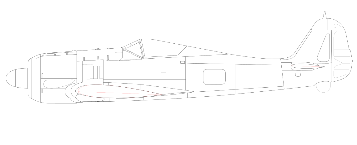
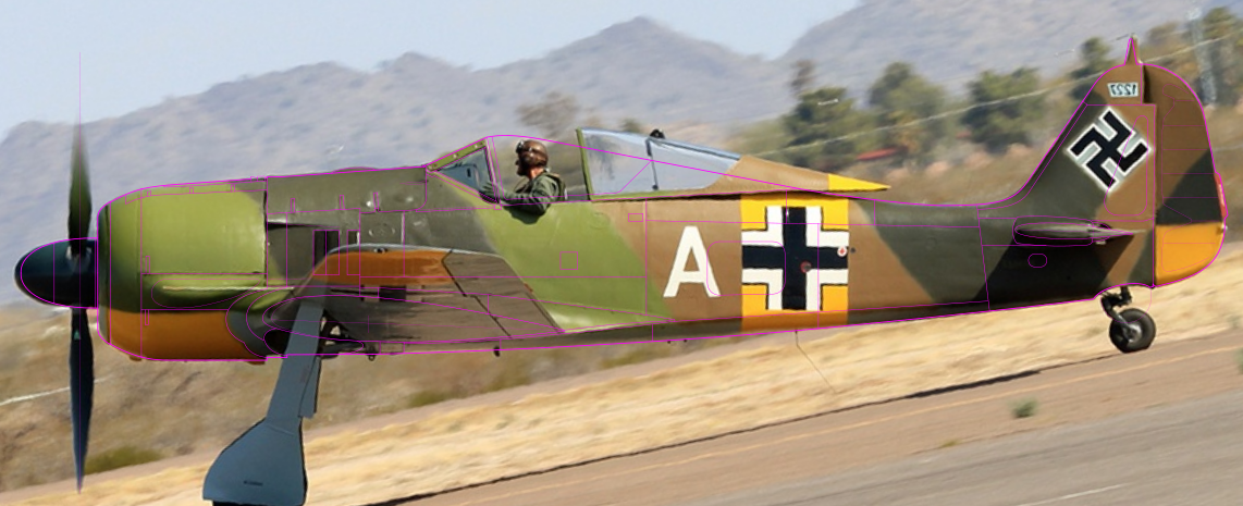
The question was whether this would match photos of actual aircraft. Therefore, I overlay it with a photo in good condition. The result was, fortunately, perfect. The spinner did not fit a bit, but this kind of part is interchangeable. |
|
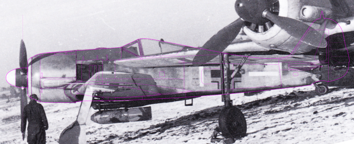
But it was still early to rejoice. Because this photo was an existing flyable aircraft. It was necessary to check whether it was restored faithfully to the original. There are many restored aircraft which have a poorly reproducted cowl or MG cover. So, I overlay it again with a photo from WW2. In the case of Fw190, there is no full-length photo in a far distance and orthogonal angle. The image below maybe the best condition. Unfortunately, the tail can not be seen. Still, it exactly matched together from the nose to the canopy. The line on the underside of the wing is perfectly known because there is a gap, probably the ETC rack was not installed properly. |
|
Only God knows which is correct, but the readers of my site already know that the total length written in a manual is often different from the fact (for example, Ki84, Ki43, Wildcat etc.). I feel 8,987 mm is more suitable when I compare with photos of actual aircraft. Many of the existing drawings (and some kits) are fitted to 8,950mm, but the tail is somehow cramped. Needless to say, my drawings adopts 8,987 mm.
|
|
I found a mistake in one sheet of factory drawings as for the windscreen. That is the correct answer is 577mm, but 557mm is mistakenly written, Well, it's a common mistake for all human beings. At first I was deceived by this, then my drawings and photos did not match.
|
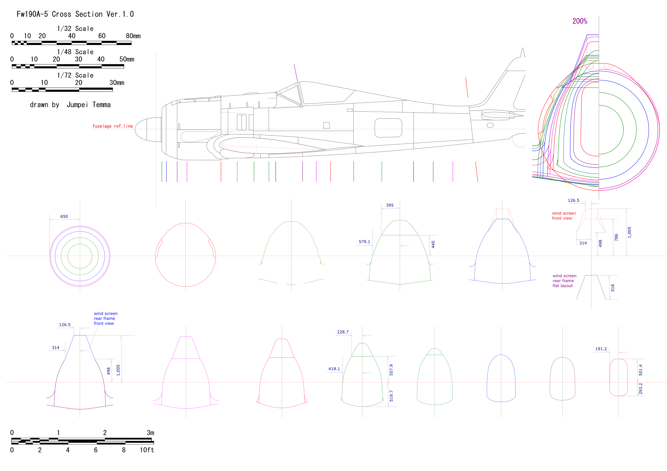
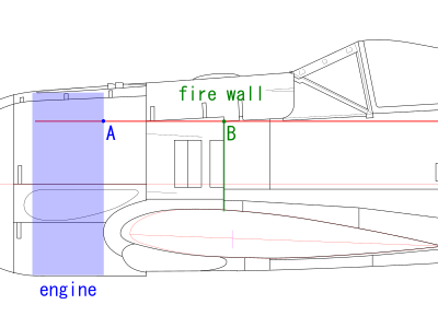
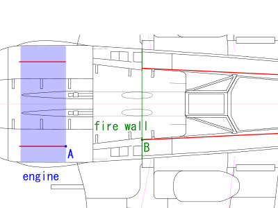
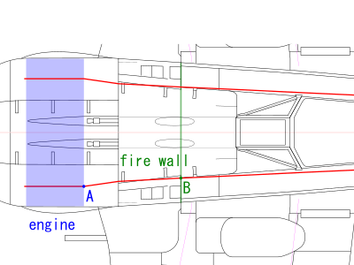
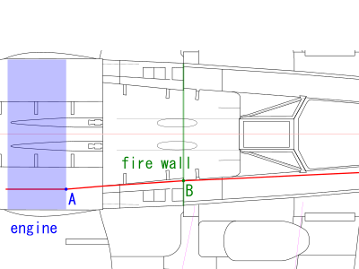
So, how do I imagine it? Please see the lower left image. Suppose the fuselage is sliced ??horizontally at the top of the firewall (point B) (red horizon line). Since the diameter of the engine part is known, the width of point A is automatically determined. The width after point B is also known from the factory drawing (as a result, it becomes almost a straight line afterward B). The result is the lower right image. Even if each line is straightened, it does not connect well. The fuselage is thin with respect to the nose. Well, how do I connect between them? |
 |
 |
|
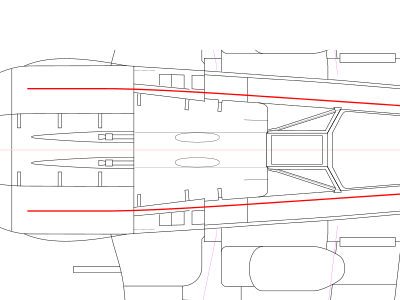
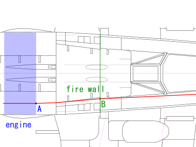
The first theory was to extend forward the line of afterward the fire wall to the rear end of the cowl as shown in the lower left image, and to connect it to point A. In other words, it was a line that assumes that there was no bending at the fire wall. However, with this theory, the constriction from the rear end of the engine to the rear end of the cowl was remarkable. The bend at point A was also remarkable. So, It was unlikely that this first theory was correct. Therefore, the second theory was to connect points A and B with a straight line as shown in the lower right. I thought this would be reasonable. Of course, in reality, there were no clear creases at points A and B, but there might be partial curve at A and B. And then, my drawings was based on this second theory. The top view line of the MG cover was determined with this theory. And based on this, each cross-sectional shape from the rear end of the cowl to the fire wall was determined. |
 |
 |
|
The point is this S-shaped curve. Old kits do not express this S curve and have a thick nose ridge outline. Of course, if the widths of cowl and canopy are correct, there will inevitably be an S-curve. That is, these widths are not correct for old kits. I mean, the canopy is too wide. I will discussed later in the kit review. Incidentally, someone may say that positions (widths) of points A and B are different. For those who say, try to make a drawing with reference to the factory drawing by yourself. |
 I think the old kits have this kind of image. The width of the fire wall is completely different. |
|
The first theory was that the panel of the MG cover was bent. The tip of the MG cover extended smoothly, but using the flexibility of the cowl panel itself, bend and narrow it slightly to fit the engine cowl cross section, and forcibly fixed with fasteners. The width of the canopyof this aircraft was narrowed when it was opened, so I thought this was also possible. However, if it was simply narrowed the width, the height might not match, so was it was processed with the fastener margin or trimmed around the bottom of the MG cover. At this time, the accessory cowl was twisted as a whole (the front upper end was moved inward) to match the engine cowl with the rear end. In this case, the extension portion of the accessory cowl might be bent like a parallel plug at the lower end and might be smooth without bend at the upper end. Alternatively, the mounting angle of the entire panel was changed inward to match the tip width (in this case, the hinge line at the lower end also changed). The second theory ws that the cross-sectional shape of the rear end of the engine cowl was changed. Actually, I had not known, but when I look at the photo of the rear end cross section of the engine cowl of A-3, it bent like a dent on the way. On the other hand, it seemed that there was no such dent in A-5 or later model (I'm not so sure), so the theory ws that the dent part was widened to the outside to accommodate the expansion of the tip of the MG cover. Regarding the accessory cowl, the way of thinking was basically the same as the first theory. |
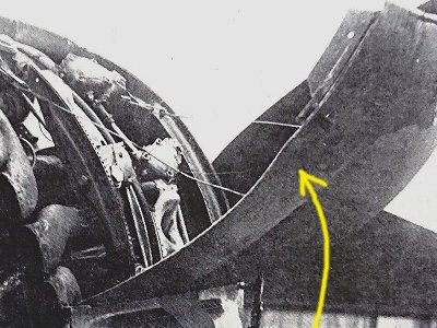 This photo is A-3 captured by the RAF (referred from FAOTW p102). There is a dent at the arrow.
|
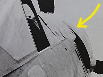 Is it A-3? This is the same line, but it can be said that the exhaust portion is bulging instead of being dented.
|
|
Then I made these two theories into drawings. Both were the same as the side view. Which was the correct answer? I thought there was an intermediate that combines both. In the case of the second theory, when I made the cross-sectional view, the taper at the rear end of the cowl almost disappears. So, I thought the first theory was probable. |
 This is the first theory. Red is A-5 and black is A-4. The width of the tip of the MG cover is the same for both A-4 and A-5. The accessory cowl is drawn based on the theory of changing the overall mounting angle. This is the theory of the A-5 top view that has been posted so far on this article. |
 The second theory. Black A-4 is the same as the left figure. The width of the common part of the MG cover is the same, and the tip is wider than A-5. Although it does not appear in the figure, the surface at the rear end of the engine cowl is different. |
|
Above article, I argued two theories about the A-5 nose line. To help determine which was correct or both were different, I draw top view shapes when the fuselage was cut with a horizontal plane passing through the upper end of the fire wall. In the photo of A-5, the rear end of the cowl seemed to be tapered depending on the angle, and the first theory seemed to me closer to the impression of photos. |
 This is the first theory. I think this line is reasonable. |
 This is the second theory. There is not much taper of the engine cowl. |
|
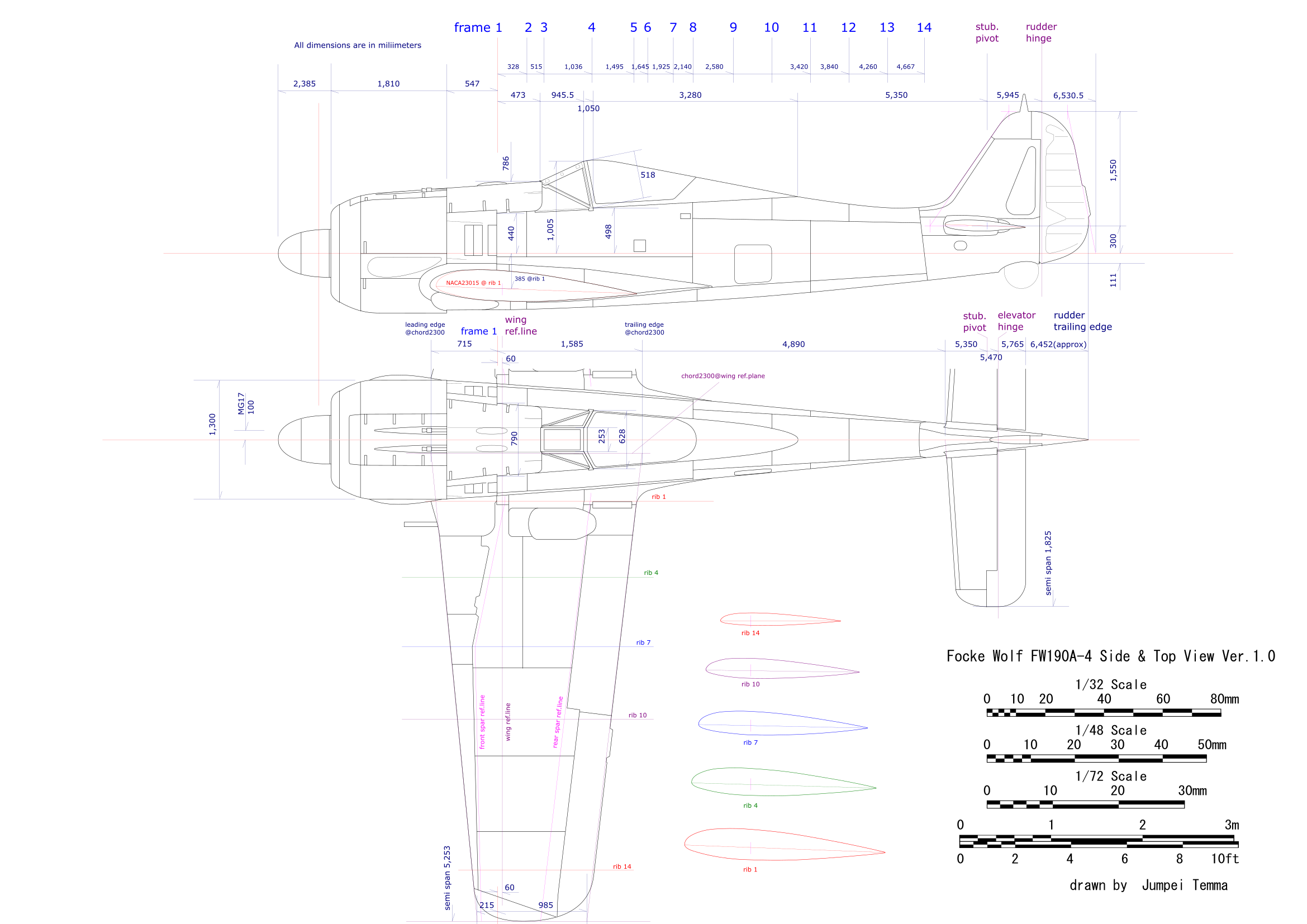
Trimaster 1/48 A-8 The area around the MG cover is 1.5mm wide. The cowl is 1mm wide and 2mm short. The rear fuselage is 1mm shorter. The canopy is a little less than 1mm wide. The nose ridge (MG cover) is thick and the engine cowl is thick and short. A typical line of "old kits" of above article. However, many people think that this is the best because of the old brand image (it depends on each person, and I do not deny it). After the disappearance of Trimaster, it is sold by Dragon.Hasegawa old 1/48 A-4 It is 2mm wide near the MG cover. The engine cowl is 1.5mm wide and 2mm short. The rear fuselage is 1.5mm shorter. The canopy is 1mm wide. The impression of the fuselage is very similar to the Trimaster. This is also a so-called old kits.Eduard old 1/48 A-5 The cowl length and overall length are accurate. However, the area around the MG cover is 1.5mm wide and the canopy is 1.5mm wide. The engine cowl looks like a drum can (with no taper), and the MG cover is wide as well. Somehow, the impression is sexually unattractive and unpolished. The current 1/72 kit is a scale down of this old 1/48 (the above dimensions are converted to 1/72 kit). The current D-9 is based on this old kit. In other words, the nose is thick and uncorrect.Hasegawa new 1/48 A-5 The area around the MG cover is 0.5mm wide. The width of the cowl is 0.5mm narrow. The cowl length is accurate. The rear fuselage length is also accurate. The canopy is a little less than 1mm wide. The line of the nose and the length of the cowl can be highly evaluated as being different from the conventional kit. Unfortunately, the reproducibility of the cross-sectional shape of the fuselage is not good.Eduard new 1/48 A-4 The area around the gun cover is 0.5mm narrow. The length of the cowl and rear fuselage is unknown (information requested). Canopy width is almost accurate. There is a feeling that the fineness of the nose ridge is emphasized a little, but at the moment it is the best of 1/48. The cross-sectional shape of the fuselage is also better than that of Hasegawa new kit. There are also A-3, A-5, A-8, etc. The old series has a 4-digit model number. The new series has 5 digits (example: 82142), so be careful when purchasing.Airfix new 1/72 A-8 The dimensions and shape of the nose are extremely accurate. In addition, the cross-sectional shape and length of the fuselage are perfect. 1/72 best kit for outline. Fitting of parts and molding are standard of Airfix's red box series. In other words, it's not good. It would be perfect if these were good. All the 1/72 kits other than Airfix new have a thick nose when I saw the finished works, so every kit is NG.Regarding the dimensions, there may be some mistakes in my measurement, so please let me know if you notice anything. For the time being, I describe the main dimensions at 1/48 of the actual aircraft. MG cover tip width : 18.5 mm (A-4 and A-5 are the same in the above first theory. 19.3 mm in A-5 in the second theory), fire wall top width (lower end of MG cover crank) : 16.5 mm, engine cowl maximum width (excluding bulges on both sides) : 27.1 mm, engine cowl length : 26.3 mm, windscreen lower end width : 13.1 mm, windscreen front edge width (up to the edge of the frame) : 5.3 mm. For other dimensions, please calculate from the actual size in my drawings.
|
This is the end of the Fw190 drawing series. There are no plans for the bottom view and front view, because it is sufficient to see the existing drawings. There is no plan to draw the Ta152 drawing because there is no material.
|
| 1 | New edition The Famous Airplane Of The World No.78 Focke-Wolf Fw190 | Bunrin-do |
| 2 | Old edition The Famous Airplane Of The World Focke-Wolf FW190 1973 No.6 | Bunrin-do |
| 3 | Modeler's Eye 4 Focke-Wolf Fw190D "Dora" | Dainippon-kaiga |
| 4 | Focke Wulf Jagdflugzeug Fw190A Fw190"Dora" Ta152H | Rogge GmbH |
| 5 | Focke Wolf Fw 190 In Action aircraft no.19 | Squadron/Signal Publications |
| 6 | Fw 190 In Action aircraft no.170 | Squadron/Signal Publications |
| 7 | Walk Around Fw 190D Walk Around Number 10 | Squadron/Signal Publications |
| 8 | Walk Around Focke-Wulf Fw-190 A/F Walk Around Number 22 | Squadron/Signal Publications |
| 9 | Monogram Close Up FW 190 F | Monogram |
| 10 | Monogram Close Up FW 190 D | Monogram |
| 11 | Monogram Close Up 24 Ta 152 | Monogram |
| 12 | Production Line To Frontline 5 Fw 190 | Osprey |
| 13 | Aircraft of the Ace 6 Focke-Wulf Fw 190 Aces of the Russian Front | Osprey |
| 14 | Aircraft of the Ace 9 Focke-Wulf Fw 190 Aces of the Western Front | Osprey |
| 15 | Aircraft of the Ace 20 German Night Fighter Aces of World War 2 | Osprey |
| 16 | Aircraft of the Ace 92 Fw 190 Defence of the Reich Aces | Osprey |
| 17 | Aircraft of the Ace 101 Luftwaffe Viermot Aces 1942-45 | Osprey |
| 18 | Aircraft of the Ace 116 Aces of Jagdgeschwader 3 'Udet' | Osprey |
| 19 | Aircraft of the Ace 134 Jagdgeschwader 1 'Oesau' Aces 1939-45 | Osprey |
| 20 | Aviation elite 1 Jagdgeschwader 2 'Richthofen' | Osprey |
| 21 | Aviation elite 6 Jagdgeschwader 54 'Grunherz' | Osprey |
| 22 | Aviation elite 20 Luftwaffe Sturmgruppen | Osprey |
| 23 | Aviation elite 27 Jagdverband 44 Squadron of Experten | Osprey |
| 24 | Osprey Duel 1 P-51 Mustang vs Fw 190 Europe 1943-45 | Osprey |
| 25 | Osprey Duel 24 Fw 190 Sturmbocke vs B-17 Flying Fortress Europe 1944-45 | Osprey |
| 26 | Osprey Duel 39 La-5/7 vs Fw 190 | Osprey |
| 27 | Monografie 01 Focke-Wolf FW 190 vol.1 | Kagero |
| 28 | Monografie 04 Focke-Wolf FW 190 vol.2 | Kagero |
| 29 | Monografie 05 Focke-Wolf FW 190 vol.3 | Kagero |
| 30 | Monografie 06 Focke-Wolf FW 190 vol.4 | Kagero |
| 31 | Miniatury Lotnicze 4 JG 2 Richthofen 1942-1943 | Kagero |
| 32 | Miniatury Lotnicze 6 JG 5 Eismeer 1942-1945 | Kagero |
| 33 | Miniatury Lotnicze 14 JG 1 Oesau 1944-1945 | Kagero |
| 34 | Miniatury Lotnicze 19 JG 301 Wilde Sau | Kagero |
| 35 | Miniatury Lotnicze 25 JG 26 Schlageter Vol.2 | Kagero |
| 36 | Miniatury Lotnicze 27 JG 1 Oesau 1939-1943 | Kagero |
| 37 | Miniatury Lotnicze 30 JG 11 | Kagero |
| 38 | Miniatury Lotnicze 35 JG 52 vol.2 | Kagero |
| 39 | Bitwy Lotnicze 07 Luftwaffe nad Tunezja (1) | Kagero |
| 40 | Bitwy Lotnicze 10 Luftwaffe nad Tunezja (2) | Kagero |
| 41 | Jagdwaffe vol3sec4 The War In Russia January-October 1942 | Classic Publications |
| 42 | Jagdwaffe vol4sec1 Holding The West 1941-43 | Classic Publications |
| 43 | Jagdwaffe vol4sec2 The Mediterranean 1942-1943 | Classic Publications |
| 44 | Jagdwaffe vol4sec3 The War In Russia November1942-December1943 | Classic Publications |
| 45 | Jagdwaffe vol4sec4 The Mediterranean 1943-1945 | Classic Publications |
| 46 | Jagdwaffe vol5sec1 Defending The Reich 1943-44 | Classic Publications |
| 47 | Jagdwaffe vol5sec2 War In The East 1944-1945 | Classic Publications |
| 48 | Jagdwaffe vol5sec3 Defending The Reich 1944-1945 | Classic Publications |
| 49 | Jagdwaffe vol5sec4 Jet Fighters And Rocket Interceptors 1944-1945 | Classic Publications |
| 50 | Nachtjaeger Vol 2 Luftwaffe Night Fighter Units 1943-1945 | Classic Publications |
| 51 | Schlachtflieger Luftwaffe Ground-Attack Units 1937-1945 | Classic Publications |
| 52 | Monografie Lotnicze 17 Focke-Wulf Fw-190 A/F/G cz.1 | AJ-Press |
| 53 | Monografie Lotnicze 18 Focke-Wulf Fw-190 A/F/G cz.2 | AJ-Press |
| 54 | Monografie Lotnicze 21 Focke-Wulf Fw-190 D,Ta 152 | AJ-Press |
| 55 | Flugzeug Profile 9 Focke Wulf Fw 190 | Flugzeug Publikations |
| 56 | Flugzeug Profile 45 Focke Wulf Fw 190 Varianten | Flugzeug Publikations |
| 57 | Luftwaffe At War 0 Focke Wolf 190 The Birth of the Butcher Bird 1939-1943 | Greenhill |
| 58 | Luftwaffe At War 18 Luftwaffe Over Finland | Greenhill |
| 59 | Luftwaffe At War 19 Luftwaffe Aces of the Western Front | Greenhill |
| 60 | Focke Wulf Ta 152 The story of the Luftwaffe's Late-War, High-Altitude Fighter | Schiffer |
| 61 | Aircraft of the Luftwaffe Fighter Aces I A Chronicle in Photographs | Schiffer |
| 62 | Aircraft of the Luftwaffe Fighter Aces II A Chronicle in Photographs | Schiffer |
| 63 | Luftwaffe im Focus Edition No 1-12,16 | Luftfahrtverlag-Start |
| 64 | Luftwaffe im Focus Edition Spezial 1-2 | Luftfahrtverlag-Start |
| 65 | Broken Eagles 1 FW190D | Fighter Pictorials |
| 66 | History, Camouflage, and Markings of JV 44 and JG 6 Focke-Wulf 190 D-9s No.72-1 | Exparten Decals |
| 67 | History, Camouflage, and Markings of JV 44 and JG 6 Focke-Wulf 190 Ds No.3 | Exparten Decals |
| 68 | EagleFiles #1 Doras-of-the-Galland-Circus | Eagle Edition |
| 69 | EagleFiles #2 Yellow 10 The story of the ultra-rare Fw 190 D-13 | Eagle Edition |